
Service manual


MD-R2
– 20 –
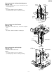
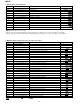
e) TEMP setting
Step 1 Testmode STOP state [ t s m e ]
Step 2
Press the ENTER button seven times.
EEPROM setting menu [E E P R O M _ S E T]
Step 3 Press once the MD PLAY button. Focus setting menu [ _ _ F o c u s _ _ _ ]
Step 4
Press the ENTER button four times.
TEMP setting menu [ _ _ _ T e m p _ _ _ ]
Step 5 Press once the MD PLAY button. TEMP reference value setting [ T E M P _ _ ]
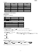
Step No.
Setting Method
Remarks Display
•
: Setting volue, : Measurement value
• When the jog key is turned upward while the setting is displayed, the setting increases, and a new setting is stored in LSI.
• When the jog key is turned downward while the setting is displayed, the setting increases, and a new setting is stored in LSI.
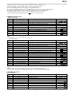
Step 1
EJECT state (or mechanism-less state)
[ _ _ E J E C T _ _ _ ]
Step 2
Press the DELETE/CLEAR button.
TEMP reference value setting [ T E M P _ _ ]
Step No.
Setting Method
Remarks Display
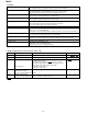
f) CONTROL setting
Step 1 Testmode STOP state [ t s m e ]
Step 2
Press the ENTER button seven times.
EEPROM setting menu [E E P R O M _ S E T]
Step 3 Press once the MD PLAY button. Focus setting menu [ _ _ F o c u s _ _ _ ]
Step 4
Press the ENTER button five times.
CONTROL setting menu [ _ C o n t r o l _ _ ]
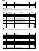
Step 5 Press once the MD PLAY button. CONTROL 1 setting [ C O N T R L 1_ ]
Step 6 Press once the ENTER button. CONTROL 2 setting [ C O N T R L 2_ ]
Step 7 Press once the ENTER button. Setting of spin kick level in MOVE state [ S P K L E V m_ ]
Step 8 Press once the ENTER button. Setting of readjustment interval time (minutes) [ A D J T T M_ _ ]
Step 9 Press once the ENTER button. Setting of equalizer coefficients A and D (high reflection) [ H D E Q A D_ _ ]
Step 10 Press once the ENTER button. Setting of equalizer coefficients A and D (low reflection pit) [ L D E Q A D_ _ ]
Step 11 Press once the ENTER button. Setting of equalizer coefficients A and D (low reflection groove) [ G D E Q A D_ _ ]
Step 12 Press once the ENTER button. Setting of equalizer coefficients B and C (high reflection) [ H D E Q B C_ _ ]
Step 13 Press once the ENTER button. Setting of equalizer coefficients B and C (low reflection pit) [ L D E Q B C_ _ ]
Step 14 Press once the ENTER button. Setting of equalizer coefficients B and C (low reflection groove) [ G D E Q B C_ _ ]
Step 15 Press once the ENTER button. Setting of autolevel slicer gain (high reflection) [ H A L S G_ _ _ ]
Step 16 Press once the ENTER button. Setting of autolevel slicer gain (low reflection pit) [ L A L S G_ _ _ ]
Step 17 Press once the ENTER button. Setting of autolevel slicer gain (low reflection groove) [ G A L S G_ _ _ ]
Step 18 Press once the ENTER button. Setting of autolevel slicer offset (high reflection) [ H A L S O F_ _ ]
Step 19 Press once the ENTER button. Setting of autolevel slicer offset (low reflection pit) [ L A L S O F S_ ]
Step 20 Press once the ENTER button. Setting of autolevel slicer offset (low reflection groove) [ G A L S O F S_ ]
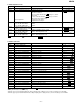
Step No.
Setting Method
Remarks Display
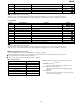
Step 1
EJECT state (or mechanism-less state)
[ _ _ E J E C T _ _ _ ]
Step 2
Press the NAME/TOC EDIT button.
CONTROL 1 setting [ C O N T R L 1_ ]
Step 3 Press once the ENTER button. CONTROL 2 setting [ C O N T R L 1_ ]
Step No.
Setting Method
Remarks Display
• : Setting volue
• When the jog key is turned upward while the setting is displayed, the setting increases, and a new setting is stored in LSI.
• When the jog key is turned downward while the setting is displayed, the setting increases, and a new setting is stored in LSI.
• CONTROL 1
Pit 7 : High frequency superposition ON/OFF in record mode (0:OFF, 1:IN)
Pit 6~4 : Play start SD number (30 to 100 sector, 10 sector step)
Pit 2~0 : High speed jump over-run (384 to 830 lines, 64 lines step)
• CONTROL 2
Pit 4~0 : EEPROM version (a~)