
Service manual


MD-R2
– 22 –
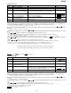
10. INNER mode
Step 1 Testmode STOP state [ t s m e ]
Step 2
Press the NAME/TOC EDIT button.
INNER menu [ _ _ I N N E R _ _ ]
Step 3 Press once the MD PLAY button. INNER switch position measurement [s c ]
(SUBQ address and C1 error are also indicated.)
Step 4 Press once the MD STOP button. INNER menu [ _ _ I N N E R _ _ ]
Step No.
Setting Method
Remarks Display
• : Adress
• Press the MD STOP button while the INNER menu is displayed, to shift to the TEST mode STOP state.
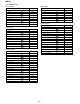
11. EJECT mode
Step 1 Testmode EJECT state [ _ _ E J E C T _ _ _ ]
Step 2 Press oncethe DISPLAY/ Max. power output state [ x p w _ _ _ _ _ _ _ ]
CHARACTER button.
Step 3 Press once the DISPLAY/ Record power output state [ r p w _ _ _ _ _ _ _ ]
CHARACTER button.
Step 4 Press once the DISPLAY Playback power output state [ p p w _ _ _ _ _ _ _ ]
CHARACTER button.
Step 5
Press the DELETE/CLEAR button.
TEMP setting of EEPROM setting
(Refer to TEMP setting of EEPROM)
Step 6
Press the NAME/TOC EDIT button.
CONTROL setting of EEPROM setting
(Refer to CONTROL setting of EEPROM)
Step No.
Setting Method
Remarks Display
Lead-in switch position measurement mode
Note: Adjust the lead-in switch position to 5FF85 to FFD2.
1. Loosen the screw (A) x 2 pcs. which fix the mechanism switch PWB.
2. Retighten the screw, pressing the mechanism switch PWB in the arrow direction, and then measure the lead-in switch position again.
After position adjustment fix with the three screws (A). (See Fig. 22.)
Note: After tightening the two screws on the PWB apply Screw Lock.
Loosen the
three screws (A).
Lead-In Switch
Mechanism Switch PWB
Figure 22
Forced rotation of loading motor
While the display indication is test mode STOP state or EJECT state,
the loading motor can be forcibly rotated by press theVOL UP/DOWN
button.