
Service manual


– 23 –
MD-R2
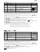
Figure 23-1 Optical Pickup Grating Deviation
Measuring Method
Mechanism Adjustment
1. Optical pickup grating inspecting method
After the automatic adjustment is performed in the AUTO
mode (test mode) with the aid of high refection MD disc
("COMPLATE" is displayed), the Lissajous's waveform (x-y) is
adjusted.
1. Slightly loosen the 3 screws of spindle moto, and maken an
adjustment, observing the Lissajous's waveform.
2. After adjustment tighten the screw in arder of 1 , 2 , 3 .
OSILLOSCOPE
GND CH1 CH2
XY
42 pin of IC 1101
GND (TP1131)
26 pin of IC 1101
EOUT (TP1133)
25 pin of IC 1101
FOUT (TP1132)
100K
470p
470p
a
b
LISSAJOUS'S WAVEFORM
Less thana:b = 3:1
100K
Figure 23-2
1
2
3
1
2
3
adjusting
hole
Spindle motor
Check the Lissajou's waveform,
shifting the mounting position with
a screwdriver (to be fitted into the
disc motor adjusting hole).
Spindle Motor
Adjusting hole
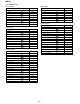
2. Jitter adjustment and checking method
Figure 23-3 Jitter connection diagram
jitter Meter
1pin of IC 1201 (TP1274)
EFMMON
88 pin of IC 1201 (TP1275)
GND
After performing automatic adjustment in AUTO mode of
TEST mode using the low reflection MD disc, check this jitter
in pit continuous playback and groove continuous playback
mode.
Figure 23-4
5P extension flat cable
QCNWK0109AFZZ
2P extension connector
QCNWK0059AFZZ
CNP1601(Bottom side)
CNP1602
CNP1252
CNP1603
CNP1604(Bottom side)
CNP1101
MD Main PWB
6P-2P extension connector
QCNWK0107AFZZ
28Pextension flat cable
QCNWK0108AFZZ
Extension PWB for service
(RUNTK0457AFZZ)
Fit the extension PWB for service to the mechanism
From Optical
Pickup Unit
From Magnetic Head
From
motor
From mecha-
nism switch
PWB