
Service manual


MD-R2
– 8 –
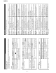
DISASSEMBLY
Caution on Disassembly
Follow the below-mentioned notes when disassembling
the unit and reassembling it, to keep it safe and ensure
excellent performance:
1. Take the minidisc out of the unit.
2. When disassembling the machine, be sure to withdraw
the power plug from the socket in advance.
3. When disassemble the parts, remove the nylon band or
wire holder as necessary.
To assemble after repair, be sure to arrange the wires as
they were.
If a screw of different length is fitted to the MD mecha-
nism (the screw of the part to be fitted to the MD
mechanism chassis), it may contact the optical pickup,
resulting in malfunction.
4. When repairing, pay due attention to electrostatic charges
of IC.
1 Top Cabinet 1. Screw ..................... (A1) x5 8-1
2 Rear Panel 1. Screw ..................... (B1) x5 8-2
3 MD Unit 1. Screw .................... (C1) x4 8-2
2. Flat Cable ...............(C2) x1
3. Socket .................. (C3) x1
4 Front Panel 1. Screw .................... (D1) x5 8-2
2. Flat Cable ...............(D2) x1
3. Socket ................... (D3) x1
5 Main PWB 1. Screw ..................... (E1) x6 8-2
(with Transformer)
6 Jog Dial 1. Knob ....................... (F1) x1 8-3
2. Nut .......................... (F2) x1
7 Display PWB 1. Screw .................. (G1) x10 8-3
2. Knob ...................... (G2) x2
8
Headphones PWB
1. Screw .................... (H1) x1 8-3
9 Switch PWB 1. Screw ..................... (J1) x5 8-3
10 MD Mechanism 1. Screw ..................... (K1) x4 8-4
Unit
11 MD Main PWB 1. Screw ..................... (L1) x2 9-1
2. Socket .................... (L2) x6
12 MD Mechanism 1. Screw .................... (M1) x4 9-2
REMOVAL
PROCEDURE
STEP
FIGURE
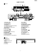
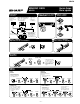
Figure 8-1
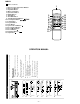
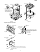
Figure 8-2
Figure 8-3
Top Cabinet
(A1)x1
ø3x10mm
(A1)x1
ø3x10mm
(A1)x3
ø3x10mm
(G1)x10
ø3x10mm
(J1)x5
ø3x10mm
Display PWB
Switch PWB
Headphone
PWB
(H1)x1
ø3x10mm
(F1)x1
(F2)x1
(G2)x2
washer
Front
Panel
Front Panel
Rear Panel
(B1)x5
ø3x10mm
(E1)x2
ø4x8mm
(D1)x1
ø3x8mm
(E1)x3
ø3x10mm
(E1)x1
ø3x10mm
(C1)x4
ø3x6mm
(D1)x1
ø3x8mm
(D1)x3
ø3x8mm
MD Unit
Main PWB
(C3)x1
(D3)x1
(C2)x1
(D2)x1
Washer
Shield Case
(K1) x 2
ø3 x 6mm
(K1) x 2
ø3 x 6mm
MD Mechanism
Unit
Figure 8-4