INSTALLATION MANUAL DIGITAL FULL COLOR MULTIFUNCTIONAL SYSTEM MODEL MX-4140N/5140N MX-4141N/5141N Parts marked with " " are important for maintaining the safety of the set. Be sure to replace these parts with specified ones for maintaining the safety and performance of the set. SHARP CORPORATION This document has been published to be used for after sales service only. The contents are subject to change without notice.
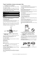
MX-5141N Transit, Installation (using) environment,6HUYLFH 0DQXDO Note 1. Installing (use) conditions (3) Before installing the machine, check that the following installing (use) conditions are satisfied. If the installing (use) conditions are not satisfied, the machine may not display full performances, resulting in troubles. It may also cause safety problems. Therefore, be sure to arrange the installing (use) conditions before setting up the machine. No.
(5) Vibration Humidity㧔RH㧕 Avoid installation near a machine which produces vibrations. 85% If vibrations are applied to the copier machine, copy images may be deflected and a trouble may be caused. 60% 20% Operational environment Temperature: 10 to 35C Humidity: 20 to 85% RH F.
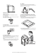
? When repairing or replacing an electronic part, perform the procedure on an anti-static mat. 2. Transit and delivery No. 1 2 Content Implements, facility, and man power Delivery Method Use a forklift. (If no forklift is available, manpower of two persons is required.) Transit must be made in packed condition. A. Implements, facility, and manpower It is recommendable to use a forklift for bringing in the machine for safety. If no forklift is available, man-power of two persons is required.
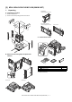
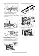
MX-5141FN 6HUYLFH 0DQXDO [2] MX-4140N/4141N/5140N/5141N (MAIN UNIT) 1. Unpacking A. Unpacking procedure 1) Remove the PP band. 2) Remove the internal packing pads with the machine. C. Packed items check B. Removal of the fixing tape and protection material 1 *1 No. 1 2 3 Name Developer *1 Operation manual Operation manual pocket *1: North America only.
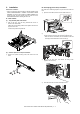
2. Installation B. Developing (each color) installation Note before installation * When connecting the main unit with the optional STAND/1 X 500 SHEET PAPER DRAWER or STAND/2 X 500 SHEET PAPER DRAWER, first unpack and install the PAPER DRAWER then unpack the main unit and securely place the main unit on the PAPER DRAWER before installing the main unit. Be careful not to attach fingerprints or oily dirt on the DV roller surface. 1) Open the front cabinet, and remove the waste toner box. A.
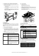
5) 8) Remove the screws. Install the DV cover in the arrow direction A. * When installing the DV cover, be sure to engage the pawl with the boss. 6) 7) Hold the sections A, and remove the DV cover in the arrow direction (B). 9) Secure the DV cover with the two screws. Supply developer (Packed items) in the developer unit. * Shake the bag of developer with unopened state. After stirring toner and developer in the bag, supply it to the developing unit.
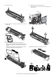
11) Install each developer unit. * When installing the developer unit, be sure to check that the DV lock lever is open. C. Set the control level for the reference toner density 1) With the front cabinet open, connect the power plug to the power outlet. 2) Turn ON the main power switch of the machine and the power switch on the operation panel. 3) Enter the SIM25-2 mode. ǂǂǂ6,08/$7,21ǂǂ12 7(67 &/26( $8720$7,& '(9(/23(5 $'-8670(17 $7 '(9( $'-B/B. $7 '(9( 92B0B.
2) Open the front cabinet, and pull the toner cartridge out slowly and horizontally. 2) Detach the LSU cleaning bar from the front cover. 3) Turn the felt side of the cleaning bar downward and insert it. Slide it back and forth a few times to clean the LSU dust-proof glass. 4) Replace the LSU claning bar to the front cover and attach the waste toner box. Close the front cabinet. * Be sure to install the color cartridges to their proper positions. Avoid installation to a different color position.
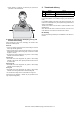
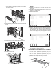
F. Installation of the operation manual pocket (2) 1) 1) Install the Operation Manual storage (Packed items) cover to the left side of the machine. a) First, insert the pawl on the lower side of the Operation Manual pocket. Tray size setup Pull out the paper tray. Gently pull the tray out until it stops. If paper remains in the tray, remove it. Then, lift the pawl on the upper side and insert it, and slide down to install.
3. Image quality check 2) A. Execution items Execute the following items. No. 1 2 3 4 Press [EXECUTE] key. [EXECUTE] key is highlighted and the image registration automatic adjustment is started. (It takes about 15 sec to complete the adjustment.
Display/ Item MAIN F Content C M Y MAIN R C M Y SUB C M Y Registration adjustment value main scanning direction (Cyan laser writing position F side) Registration adjustment value main scanning direction (Magenta laser writing position F side) Registration adjustment value main scanning direction (Yellow laser writing position F side) Registration adjustment value main scanning direction (Cyan laser writing position R side) Registration adjustment value main scanning direction (Magenta laser writing po
(2) Copy color balance and density check MEMO: Before checking the copy color balance and density, be sure to execute the following jobs. * Execute the high density image correction (Process correction) forcibly. (SIM 44-6) * Execute the half-tone image correction forcibly. (SIM 44-26) Method 1 Make a copy of the gray test chart (UKOG-0162FCZZ) and a copy of the servicing color test chart (UKOG-0326FCZZ/UKOG0326FC11), and check that they are proper. a.
a. Color copy check items (Check to confirm the following:) 1) There are 12 void areas. 4) 2) Registrations (one point for the main scanning, and one point for the sub scanning) are not shifted. The color difference in gray balance between the F and the R sides is not so great. 5) There are no white and black streaks. 3) The resolution of 5.0 (5 points) can be seen. 6) Color texts are clearly reproduced. 7) The background density is not so light.
b. Monochrome copy check items (Check to confirm the following:) 1) There are 12 void areas. 4) 2) The resolution of 4.0 (5 points) can be seen. 5) There are no white and black streaks. The background density is not so light. 3) The density difference between the F and the R sides is not so great. 6) The black low-density gradation is copied slightly.
Method 2 Method 1 Use SIM46-21 to print the color balance adjustment sheet, and check each process (CMY) black patch color balance and the black patch in order to confirm that the color balance adjustment is proper. Execute SIM 64-5 to print the print test pattern. Low density NOTE: When the PCL or the PS printer function is not provided in case of GDI printer, this method cannot be used for check. Set each set value to the default and press [EXECUTE] key. The print test pattern is printed.
(4) Copy/Printer color balance and density adjustment (Automatic adjustment) 1) 4) Enter the SIM46-74 mode. ǂǂǂ6,08/$7,21ǂǂ12 7(67 Select [FACTORY] target, and press [EXECUTE] key. When the color balance is customized by the manual color balance adjustment (SIM 46-21) according to the user's request, and the color balance is registered with SIM63-7 as the service target, if the color balance is required to be adjusted, select the [SERVICE] target.
6) The printer color balance adjustment (step 1) is automatically performed and the color balance check patch image is printed out. Set the color patch image (adjustment pattern) printed in the procedure 5) on the document table. Set the color patch image (adjustment pattern) printed in the procedure 2) on the document table. Place the color patch image so that the fine lines are on the left side. At that time, place 5 sheets of white paper on the printed color patch image (adjustment pattern).
10) When "COMPLETED THIS PROCEDURE" is displayed, the adjustment operation is completed. Cancel SIM46-74. ǂǂǂ6,08/$7,21ǂǂ12 7(67 &/26( (1*,1( $872 $'-8670(17 6(59,&( &203/(7( 7+,6 352&('85( 3/($6( 48,7 7+,6 02'( 2. 5(68/7 5(75< NOTE: The adjustment result becomes valid only when the both adjustments in the copy mode and in the printer mode are completed.