MX-M1055 MX-M1205 Administrator Machine Adjustment Guide Please keep the manual in a safe place where it will not be lost.
Caution The Machine Adjustment is provided assuming that an administrative user who has sufficient knowledge for machine maintenance and management and is responsible for them uses the adjustment. Changing adjustment values provided by the Machine Adjustment without having sufficient knowledge may lead to unexpected incidents such as insufficient print quality or product performance, increase in toner consumption and influence on machine life.
Table of Contents 1 Image Quality Adjustment....................................................................................................... 6 1.1 Laser Adjustment .......................................................................................................................... 6 1.1.1 Density Smoothing Adjustment (Auto Adjustment)...................................................................................... 6 1.1.2 Density Smoothing Adjustment (Densitometer Adjustment) ........
3 Peripheral Adjustment........................................................................................................... 20 3.1 Saddle Finisher (When the 100-sheet saddle finisher is installed) .......................................... 20 3.1.1 Staple Position Adjustment........................................................................................................................20 3.1.2 Paper Alignment Width Adjustment for Staple Position ..........................................
Void Area Unprinted area around the edges of sheet in printing Purpose of Document This document is for explaining the content, procedure and caution on each adjustment so that users in charge of machine maintenance understand and perform the machine adjustment properly. Image Loss Unscanned area around the edges of original in scanning To adjust the machine, tap the [Machine Adjustment] key in the Home Screen to open the Machine Adjustment screen.
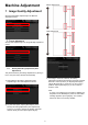
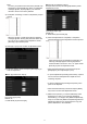
Machine Adjustment [Before Adjustment] 1 Image Quality Adjustment Select [Image Quality Adjustment] in the Machine Adjustment screen. [After Adjustment] 1.1 Laser Adjustment Select [Laser Adjustment] in the Image Quality Adjustment screen. 1.1.1 Density Smoothing Adjustment (Auto Adjustment) This performs density smoothing adjustment for printing in front / rear (main scan) direction automatically. 3) A message “Value set at Density Smoothing Adjustment (Densitometer/Visual) is cleared if executed.
4) A test patch is printed. 8) Make sure to perform [1.4.3 User Calibration] under [Settings] if you wish not to erase the adjustment values set by [1.4.1 Engine Grey Balance Adjustment] and [1.4.2 Printer Grey Balance Adjustment]) after this adjustment. Make sure to choose both the copy and printer calibrations in the calibration. 1.1.
3) A test patch containing a column of 28 patches (3-30) is printed. When the desired density is not achieved, tap the [Readjust] key and repeat steps 3) to 7). When the desired density is achieved, tap the [Back] key to return to the Laser Adjustment screen. 8) Make sure to perform [1.4.3 User Calibration] under [Settings] if you wish not to erase the adjustment values set by [1.4.1 Engine Grey Balance Adjustment] and [1.4.2 Printer Grey Balance Adjustment]) after this adjustment.
Note: To return your preferences to the factory defaults, tap the [Return to the Defaults] key. When a confirmation message appears, tap the [OK] key. The machine reboots to return to the factory defaults. ◆When [31] is selected in step 4): Example of the Density Smoothing Adjustment (Visual Adjustment) screen 3) A test patch containing a column of 28 patches (3-30) is printed. Input range: [25] to [75] Default: 50 P: POSITION (16) is fixed at [50].
1.2 4) To reflect the settings, the machine needs to reboot. When the [Register] key is tapped, a message appears prompting you to reboot the machine. Density Adjustment Select [Density Adjustment] in the Image Quality Adjustment screen. 1.2.1 Density Adjustment Automatic Execution Frequency 5) Tap the [OK] key to reboot the machine. 1.2.2 This makes a setting of frequency (condition) to perform density adjustment (process control) automatically.
1.2.3 Note: ・ When plain paper or recycled paper is used, Set [Fusing Control Settings] of [Device Control] in [System Settings]. ・ When unrecommend glossy paper is used, set paper property to print with proper weight of paper setting. ・ When an envelope is not set properly in the tray, poor fusing or crease may occur. ・ When unrecommended envelope is used, poor fusing or crease may occur. Density Adjustment (Forced Execution) This performs density adjustment (process control) forcefully.
1.4 Note: When the [Set in a Batch] checkbox is checked, Density Points 1-17 are greyed out. When this checkbox is not checked, the textbox for [Set in a Batch] is not active. (A beep sounds when the textbox is tapped.) Image Quality Adjustment Select [Image Quality Adjustment] in the Image Quality Adjustment screen. 1.4.1 Engine Grey Balance Adjustment This enables adjustment of gradation density for printing in copy mode by measuring test patch visually.
Note: When both of [Copy Calibration] and [Printer Calibration] are checked, copy calibration is first executed and then printer calibration. Note: When the [Set in a Batch] checkbox is checked, Density Points 1-17 are greyed out. When this checkbox is not checked, the textbox for [Set in a Batch] is not active. (A beep sounds when the textbox is tapped.) 5) 3) When the [Execute] key is tapped, the checked calibration starts.
4) Place the printed test patch on the document glass and tap [Execute] to start the auto adjustment. Place the test patch in portrait orientation. Note: When the printing of a test patch fails, the following message appears: Printing test patch has failed. Use A4 or 8 1/2" X 11" paper for this adjustment. Press [Execute] to print the test patch. Note: When the scanning of the test patch fails, the following message appears: Auto adjustment has failed.
1.5 Other Functions Select [Other Functions] in the Image Quality Adjustment screen. 1.5.1 Main Charger Cleaner Operation This performs main charger cleaning. 1) Select [Cleaner Operation] in the Other Functions screen. 2) To start the main charger cleaner operation, tap the [Execute] key in the Cleaner Operation screen. 3) When the cleaner operation is completed, a completion message appears. 4) To return to the Other Functions screen, tap the [Back] key. 1.5.
Note: To return your preferences to the factory defaults, tap the [Return to the Defaults] key. When a confirmation message appears, tap the [OK] key. Your preferences are returned to the factory defaults and the screen returns to the Ratio Adjustment screen. 2 Image Position/Ratio/Area Adjustment Select [Image Position/Ratio/Area Adjustment] in the Machine Adjustment screen. 2.1 2.2 Ratio Adjustment Edge Adjustment Select [Edge Adjustment] in the Image Position/Ratio/Area Adjustment screen.
2.2.2 2.3 Feed Direction Print Position Adjustment (Registration Motor On Timing) Void Area Adjustment Select [Void Area Adjustment] in the Image Position/Ratio/Area Adjustment screen. This performs print start position adjustment for printing. 2.3.1 1) Select [Feed Direction Print Position Adjust. (Registration Motor On Timing)] in the Edge Adjustment screen. Copy Image Loss Amount Settings This performs adjustment of image loss amount for scanning original in copy mode.
2.3.2 Side 2 side image loss amount: [20] Side 2 rear edge image loss amount: [20] Print Void Settings This performs adjustment of print void amount for printing. Note: To return your preferences to the factory defaults, tap the [Return to the Defaults] key. When a confirmation message appears, tap the [OK] key. Your preferences are returned to the factory defaults and the screen returns to the Void Area Adjustment screen. 1) Select [Print Void Settings] in the Void Area Adjustment screen.
2.4 2) Enter the desired values and tap the [Register] key. Off-Centre Adjustment Select [Off-Centre Adjustment] in the Image Position/Ratio/Area Adjustment screen. 2.4.1 Print Off-Centre Adjustment This performs centre position adjustment for printing. 1) Select [Print Off-Centre Adjustment] in the Off-Centre Adjustment screen. Input range: [20] to [80] (1 = 0.1 mm) Default: [50] for each Note: To return your preferences to the factory defaults, tap the [Return to the Defaults] key.
3 Peripheral Adjustment Select [Peripheral Adjustment] in the Machine Adjustment screen. Adjustable options: The saddle finisher, trimming module, finisher, punch module, and folding unit can be adjusted: The installed options are displayed as follows: Input range: One staple: [70] to [130] Two staples: [85] to [115] (1 = 0.1 mm) Default: 100 for each When the 100-sheet saddle finisher, trimming module and punch module are installed: Note: Staple position in paper feed direction cannot be adjusted.
3.1.2 Paper Alignment Width Adjustment for Staple Position 3.1.4 This performs jogger width adjustment for staple (paper width direction). Set this adjustment when the stapled stuck of paper is not aligned. This performs adjustment of fold and staple positions for saddle stitch (fold and staple) (both fold and staple positions are adjusted together). 1) Select [Fold/Staple Position Adjustment for Saddle Stitch] in the Saddle Finisher screen.
3.1.6 2) Adjust the trimming original point for saddle stitching. The 10-key pad appears when each of the textboxes is tapped. Enter the desired values. Paper Alignment Width Adjustment for Saddle Stitch/Saddle Fold This performs jogger width adjustment for saddle stitch and saddle fold. Set this adjustment when the stapled stuck of paper is not aligned. 1) Select [Paper Alignment Width Adjustment for Saddle Stitch/Saddle Fold] in the Saddle Finisher screen.
3.4 Note: Staple position in paper feed direction cannot be adjusted. Select [Punch Module] in the Peripheral Adjustment screen. Functional Restriction For 2 staples, the staple positions that can be adjusted vary depending on the paper size and the number of sheets included in a set to be stapled as the following table shows: Paper size A4R/Letter R or smaller Larger than A4R/Letter R 3.3.
3.4.2 3.5 Punch Mode Switch Folding Unit Select [Folding Unit] in the Peripheral Adjustment screen. This switches punch operation mode. High Accuracy Mode: Prioritizes punch position accuracy when punching. High Production Mode: Prioritizes speed when punching. This performs adjustment of fold position for saddle fold. 1) Select [Punch Mode Switch] in the Punch Module screen. 1) Select [Saddle Fold Position Adjustment] in the Folding Unit screen. 3.5.
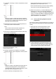
3.5.2 C-Fold Position Adjustment Diagram showing the accordion fold position This performs adjustment of fold position for C-fold. 1) Select [C-Fold Position Adjustment] in the Folding Unit screen. 2) Adjust the C-fold position for when the folding unit is installed. The 10-key pad appears when the textbox is tapped. Enter the desired value. 3.5.4 Double Fold Position Adjustment This performs adjustment of fold position for double fold.
3.5.5 Z-Fold Position Adjustment 4 Print Setting Value List This performs adjustment of fold position for Z-fold. The current setting values and the factory defaults for the 1) Select [Z-Fold Position Adjustment] in the Folding Unit screen. items in the machine adjustment can be printed. 2) Adjust the Z-fold position for when the folding unit is installed. The 10-key pad appears when each of the textboxes is tapped. Enter the desired values.
5.2 5 Layout of the 10-key Pad The behavior specifications of the 10-key pad are as follows: When the 10-key pad is opened, the numerical display shows by default the value currently shown in the textbox or the factory default value. A new entry made with the numeric keys of 0 to 9 overwrites a value currently shown in the numerical display. The 10-key pad is closed by tapping the [OK] key. When the 10-key pad is closed, the value in the numerical display is reflected in the textbox.
ADJ-EX-1