
NUJD440


SIM02E-003A
5
Annex
(normative)
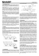
【D e sig n lo a d 】
T a b le.A 1 D esign loa d b y c lip p ing on lon g fra m es (se e F ig. A 1) T a b le.A 3 D esign loa d b y u s ing B olt H oles (s e e F ig. A 3)
clip center position bolts & nuts
(e: m m ) dow nw ard force upw ard force (position of using holes) dow nw ard force upw ard force
e = 3 0 0 3,600P a 2,400P a 4points at "c" holes 3,600P a 2,400P a
216 < e <430 2,400P a 2,400P a 4points at "b" holes 3,600P a 2,400P a
0 < e <527 1,600P a 1,600P a 2points at "c" & 2 points at opposite "b" holes 2,400P a 1,600P a
T a b le.A 2 D esign loa d b y c lip p ing on s h o rt fram e s (s e e F ig. A 2 )
clip center position
(e: m m ) dow nw ard force upw ard force
0< e <262 800P a * 800P a *
【T est lo a d 】
T a b le.A 1-1 T e s t loa d b y c lip ping o n lon g fra m es (s e e F ig. A 1 ) T a b le.A 3-1 T e s t loa d b y u sing B olt H o les (se e F ig. A 3)
clip center position bolts & nuts
(e: m m ) dow nw ard force upw ard force (position of using holes) dow nw ard force upw ard force
e = 3 0 0 5,400P a 3,600P a 4points at "c" holes 5,400P a 3,600P a
216 < e <430 3,600P a 3,600P a 4points at "b" holes 5,400P a 3,600P a
0 < e <527 2,400P a 2,400P a 2points at "c" & 2 points at opposite "b" holes 3,600P a 2,400P a
4points at "a" holes ※ ※
T a b le.A 2-1 T e s t loa d b y c lip ping o n s ho rt fram es (s e e F ig. A 2 )
clip center position
(e: m m ) dow nw ard force upw ard force
0< e <262 1200P a * 1200P a *
The Test load has been calculated w ith a safety factor of 1.5 from the design load.
* Test procedure according to IE C 61215-2:2016. T he test results are based on internal
evaluation. T he m echanical loads do not com ply w ith M Q T 16 of IE C /E N 61215:2016
design load according to IE C 61215
S harp Internal Test
design load according to IE C 61215
test load according to IE C 61215
S harp Internal Test
test load according to IE C 61215
※ T his m ounting m ethod is only for single axis trackers. T he torque lim iter device has to be
adjusted, that the m odules w ill be m oved to a secure position to avoid any m echanical
overload.
ee
Fig. A1: Clipping position on long frames
e
e
Fig. A2: Clipping position on short frames
c→
c→
←c
←c
b→ ←b
b→ ←b
a→ ←a
a→ ←a
Fig. A3: The location of Bolt Holes
Fig. A3-1: The components for BOLT & NUT
1. Spring washer 2. Washer
Material: Stainless steel Material: Stainless steel
Diameter: M8 8.2/15.4 mm Diameter: M8 8.5/15.5 mm
Thickness: 2 mm (reference value) Thickness: 1.6 mm (reference value)
3. Bolt 4. Nut
Material: Stainless steel Material: Stainless steel
Size: M8 Size: M8
Diameter: M8 x 20 mm