
Instruction manual

;
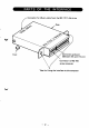
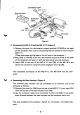
Connector cover
Figure 4
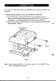
3. Connecting
the
MZ-1E14 and
the
MZ-1F11 (Figure 4)
1) Remove the cover for
the
external
output
terminal (I/O
BUS)
at
the back
of
the
computer main unit by unscrewing
the
two screws for mounting the
MZ-1
F11.
(These two screws
will be used
to
fix this unit
to
the
computer.)
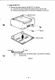
2)
Plug CNS
of
the
MZ-1
E14 into the external
output
terminal at the back
of
the computer and secure it with the
two
screws you just removed.
3)
Insert CN3
at
the
rear
of
the
MZ-1F11 into CN4
of
the MZ-1E14 and
secure
the
connection using the screws originally securing CN3.
This
completes connection
of
the
MZ-1F11, the MZ-1E14 and the com-
puter.
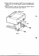
V 4. Connecting the Data Recorder (Figure
4)
The removed data recorder can be connected
as
an external unit
to
the
computer
as
follows:
1) Remove the cover for CN6 from the rear of
the
MZ-1
F11, then insert
CN1
from
the
bottom
of the data recorder into CN6.
2)
Use
the extension cable
to
be connected
to
CN1
and CN6,
if
you prefer
more distance between the data recorder and the computer main unit.
This step
completes
the
procedure. Switch
on
the power, and check oper-
ation.
-6-