
DIGITAL MULTIMEDIA PROJECTOR OPERATION MANUAL MODEL PG-M25X


Basic Operation
-35
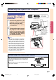
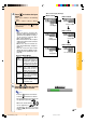
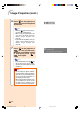
"On-screen Display (Example)
Using
Analog RGB
Using
Component
INPUT 2 Mode
INPUT 3 Mode
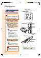
4 Press and select the input
mode.
• Each press switches in the following
order’
→ INPUT 1 → INPUT 2 → INPUT 3 → INPUT 4
• You can also use the on the
GyroRemote.
Note
• When no signal is received, “NO
SIGNAL” will be displayed. When a
signal that the projector is not pre-
set to receive is received, “NOT
REG.” will be displayed.
• When Auto Search is ON, the input
modes with signals can be selected
(See page 91.)
• When a PC card is inserted, the
input will automatically change to
INPUT 4.
• You can select the input mode
directly by using the Button Assign
function on the GyroRemote (See
page 41.)
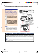
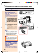
About the INPUT Modes
Used for projecting im-
ages from equipment that
sends RGB signals or
Component signals con-
nected to the DVI-DIGI-
TAL/ANALOG input port.
Used for projecting im-
ages from equipment
connected to the S-
VIDEO input terminal.
Used for
projecting
im-
ages
from equipment
connected to the VIDEO
input terminal.
When projecting from a
wireless LAN PC card or
a memory card.
INPUT 1
(RGB/
Component)
INPUT 2
(S-Video)
INPUT 3
(V
ideo
)
INPUT 4
(PC Card)
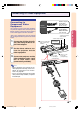
INPUT 1 Mode
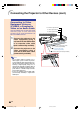
5 Press or on the Gyro-Re-
mote to adjust the volume.
Note
• Pressing will raise the volume.
Pressing
will lower the volume.
• On the GyroRemote, the volume can
be adjusted by pressing
.
• When a PC card is installed,
,
on the projector or on the
GyroRemote operate as cursor
buttons (\, |) when the OSD menu
is active.
Using
DVI digital
Using S-Video
Using Video
INPUT 4 Mode
PC Card installed
PG-M25X#E#p33_49.p65 02.4.29, 3:11 PM35