Important Information Setup & Connections Operation Buttons Basic Operation Multiple Function OPERATION MANUAL LCD PROJECTOR XG-P20XU Maintenance & Troubleshooting MODEL Appendix
Important Information Before using the LCD projector, please read this operation manual carefully. Introduction IMPORTANT For your assistance in reporting the loss or theft of your Color LCD Projector, please record the Serial Number located on the bottom of the projector and retain this information. Before recycling the packaging, please be sure that you have checked the contents of the carton thoroughly against the list of “Supplied Accessories” on page 12 . ENGLISH Model No.: XG-P20XU Serial No.
Important Information IMPORTANT SAFEGUARDS Electrical energy can perform many useful functions. This product has been engineered and manufactured to ensure your personal safety. But IMPROPER USE CAN RESULT IN POTENTIAL ELECTRICAL SHOCK OR FIRE HAZARD. In order not to defeat the safeguards incorporated into this LCD Projector, observe the following basic rules for its installation, use and servicing.
Important Information IMPORTANT SAFEGUARDS Caution Concerning the Lamp Replacement See “Replacing the Lamp” on pages 68 and 69 . LAMP REPLACEMENT CAUTION BEFORE REMOVING THE SCREW, DISCONNECT POWER CORD. HOT SURFACE INSIDE ALLOW 1 HOUR TO COOL BEFORE REPLACING THE LAMP. REPLACE WITH SAME SHARP LAMP UNIT TYPE BQC-XGP20X//1 ONLY. UV RADIATION : CAN CAUSE EYE DAMAGE. TURN OFF LAMP BEFORE SERVICING. MEDIUM PRESSURE LAMP : RISK OF EXPLOSION. POTENTIAL HAZARD OF GLASS PARTICLES IF LAMP HAS RUPTURED.
Important Information IMPORTANT SAFEGUARDS Temperature Monitor Function If the projector starts to overheat due to setup problems or a dirty air filter, “TEMP.” and “ ” will flash in the lowerleft corner of the picture. If the temperature continues to rise, the lamp will turn off, the TEMPERATURE WARNING indicator on the projector will flash, and after a 90-second cooling-off period the power will shut off. Refer to “Lamp/Maintenance Indicators” on page 67 , for details.
Important Information Outstanding Features 1. High-end LCD Projector with Ultra High Brightness • AC 220 W Lamp Use AC 220 W lamp for excellent color uniformity and ultra high brightness. 2. Computer Compatibility • Compatible with resolutions including VGA-SVGA (expanded), XGA (true resolution) and SXGA-UXGA (compressed) as well as DTV formats (480i, 480P, 720P and 1080i). 3. XGA Image Quality • OCS LCD panel enhances color uniformity.
Important Information Outstanding Features 6. Network Capability • Self-Diagnosis/Projector Status Self-diagnosis/Projector status function sends e-mail messages to a specified computer about lamp usage time and any malfunctions. • Multiple & Group Projector Control Up to 250 projectors can be controled over a network. Projector RS-232C OUT can be used for daisy chain connection.
Important Information Contents Important Information Operation Buttons Setup & Connections Introduction .......................................... IMPORTANT SAFEGUARDS ................ Outstanding Features .......................... Contents ................................................ How to Access the PDF Operation Manuals ............................................ Part Names............................................ Accessories ..........................................
Maintenance & Troubleshooting Basic Operation Lamp/Maintenance Indicators ............. Replacing the Lamp ............................. Replacing the Air Filter ........................ Troubleshooting ................................... For SHARP Assistance (U.S.A. only) .. 67 68 70 71 71 49 52 53 53 54 Appendix Connecting Pin Assignments ............. (RS-232C) Specifications and Command Settings.......................... Wired Remote Control Terminal Specifications .................................
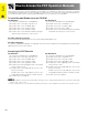
Important Information How to Access the PDF Operation Manuals PDF operation manuals in several languages are included in the CD-ROM. To utilize these manuals, you need to install Adobe Acrobat Reader on your PC (Windows or Macintosh). If you have not installed Acrobat Reader yet, you can download it from the Internet (http://www.adobe.com) or install it from the CD-ROM. To Install Acrobat Reader from the CD-ROM For Windows: 1 2 3 4 5 6 Insert the CD-ROM in the CD-ROM drive.
Important Information Part Names Numbers next to the part names refer to the main pages in this manual where the topic is explained.
Important Information Part Names Numbers next to the part names refer to the main pages in this manual where the topic is explained.
Important Information Accessories Supplied Accessories GyroRemote RRMCG1631CESA Four AAA size batteries RGB cable QCNW-5304CEZZ ø2.5–ø3.5 mm wired remote control cable QCNW-5943CEZZ USB mouse control cable QCNW-5916CEZZ Three BNC-RCA adaptors QPLGJ0107GEZZ CD-ROM UDSKA0043CEN1 LCD projector operation manual TINS-7354CEZZ Lens cap PCAPH1056CESA Power cord QACCU5013DE01 Computer audio cable (ø3.
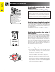
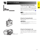
Connections Power Supply Setup & Connections Connecting the Power Cord Plug the supplied power cord into the AC socket on the rear of the projector. Power cord Make the necessary connections before proceeding. Connect the power cord to a wall outlet. The POWER indicator lights up red and the projector enters standby mode. POWER indicator • If the bottom filter cover is not securely installed, the POWER indicator flashes.
Projecting Computer Images Connecting the Projector to a Computer You can connect your projector to a computer for projection of full color computer images. Connecting to a computer using the standard 15-pin Input 1 1 2 3 4 4 Computer audio cable RGB cable Setup & Connections 3 2 Connect one end of the supplied RGB cable to the INPUT 1 port on the projector. Connect the other end to the monitor output port on the computer. Secure the connectors by tightening the thumb screws.
Projecting Computer Images • This projector uses a 5 BNC computer input to prevent deterioration of image quality. • Connect the R (PR), G/G sync (Y), B (PB), HD/C sync and VD cables (sold separately) to the correct input terminals on the projector and an RGB switcher (sold separately) connected to the computer, or connect a 5 BNC cable (sold separately) directly from the input terminals on the projector to the computer.
Projecting Computer Images Connecting to a computer using the RS-232C Port When the RS-232C port on the projector is connected to a computer with an RS-232C cable (null modem, cross type, sold separately), the computer can be used to control the projector and check the status of the projector. See pages 73 , 74 and 75 for details. Connect an RS-232C cable (null modem, cross type, sold separately) to the serial port on the computer.
Watching Video Images Connecting to a VCR, laser disc player and other audiovisual equipment using the standard video Input S-video cable (sold separately) Example Setup & Connections To S-video output terminal Video cable (sold separately) 1 VCR To video output terminal or Laser disc player 2 Audio cable (sold separately) To audio output terminals 1 2 Connect the yellow RCA connectors to the corresponding yellow VIDEO INPUT 4 terminal on the projector and the Video output terminal on the video so
Watching Component Video Images Connecting to a DVD video player, DTV decoder and other component video equipment using the 5 BNC Input 4 To audio output terminals Example 3 Setup & Connections Audio cable (ø3.
Power ON/OFF Press POWER ON on the projector or POWER on the GyroRemote. Setup & Connections POWER • The flashing green LAMP REPLACEMENT indicator shows that the lamp is warming up. Wait until the indicator stops flashing before operating the projector. • If the power is turned off and then immediately turned on again, it may take a short while before the lamp turns on. • When the projector cannot recognize GyroRemote, an onscreen display appears. Follow the instructions to activate control.
Setting Up the Screen Using the Adjustment Feet 1 3 2 Setup & Connections UP Press foot releases. Adjust height of projector and remove hands from foot releases. DOWN Rotate feet to make minor changes. • The projector is adjustable up to approximately 10° from the standard position. • When the height of the projector is adjusted, the image may become distorted (keystoned), depending on the relative positions of the projector and the screen.
LENS Button Projector GyroRemote Digital Image Adjustments This function can be used to adjust the focus, zoom, keystone, v-size and digital shift settings. Setup & Connections ENTER 1 Press LENS to select mode. Each time LENS is pressed, the screen changes as shown on the left. 2 Press ENTER to display test pattern. 3 Press ∂/ƒ/ß/© to make adjustments. (Press / to make adjustments on the GyroRemote.) 4 a. Press LENS until normal screen appears. b.
Adjusting the Projection Distance Position the projector perpendicular to the screen with all feet flat and level to achieve an optimal image. Move the projector forward or backward if the edges of the image are distorted. Setup & Connections • The projector lens should be centered in the middle of the screen. If the lens center is not perpendicular to the screen, the image will be distorted, making viewing difficult. • Position the screen so that it is not in direct sunlight or room light.
Adjusting the Projection Distance Upper and Lower Lens Shift Position • This projector is equipped with a lens shift function that lets you adjust the projection height. • Adjust to match the setup configuration. Setup & Connections Screen size: 100 inches (254 cm) WIDE Mode: 16:9 Standard Lens as an example Screen Lens center Upper lens shift position H: 2 1 (62.
Adjusting the Projection Distance Standard Lens Throw distance ratio 1:1.8 to 2.4 Screen size (4:3) (X) Diag. Width Height Projection distance (L) Maximum (l1) Minimum (l2) Setup & Connections NORMAL Mode (4:3) Lens center to the lower edge of the screen (H) Upper lens shift position (h1) Lower lens shift position (h2) 300 240 180 47 0 (14.3 m) 36 2 (11.0 m) 7 6 (228.6 cm) 0.0 (0.0 cm) 200 160 120 32 2 (9.8 m) 24 3 (7.4 m) 5 0 (152.4 cm) 0.0 (0.
Adjusting the Projection Distance Setup & Connections AN-W6EZ Throw distance ratio 1:1.3 to 1.7 NORMAL Mode (4:3) Screen size (4:3) (X) Diag. Width Height Projection distance (L) Maximum (l1) Minimum (l2) Lens center to the lower edge of the screen (H) Upper lens shift position (h1) Lower lens shift position (h2) 300 240 180 33 11 (10.3 m) 26 1 (7.9 m) 7 6 (228.6 cm) 0.0 (0.0 cm) 200 160 120 22 6 (6.9 m) 17 3 (5.3 m) 5 0 (152.4 cm) 0.0 (0.
Adjusting the Projection Distance AN-T6EZ Throw distance ratio 1:2.5 to 3.3 Screen size (4:3) (X) Diag. Width Height Projection distance (L) Maximum (l1) Minimum (l2) Setup & Connections NORMAL Mode (4:3) Lens center to the lower edge of the screen (H) Upper lens shift position (h1) Lower lens shift position (h2) 300 240 180 65 9 (20.0 m) 50 5 (15.4 m) 7 6 (228.6 cm) 0.0 (0.0 cm) 200 160 120 43 8 (13.3 m) 33 5 (10.2 m) 5 0 (152.4 cm) 0.0 (0.
Adjusting the Projection Distance Setup & Connections AN-P9MX Throw distance ratio 1:0.9 NORMAL Mode (4:3) Screen size (4:3) (X) Diag. Width Height Projection distance (L) Lens center to the lower edge of the screen (H) 300 240 180 18 1 (5.5 m) 7 6 (228.6 cm) 200 160 120 12 0 (3.7 m) 5 0 (152.4 cm) 150 120 90 9 0 (2.7 m) 3 9 (114.3 cm) 100 80 60 5 11 (1.8 m) 2 6 (76.2 cm) 84 67 50 4 11 (1.5 m) 2 1 (64.0 cm) 72 58 43 4 2 (1.
Adjusting the Projection Distance AN-P48EZ Throw distance ratio 1:4.6 to 6.1 Screen size (4:3) (X) Height Width Diag. Projection distance (L) Minimum (l2) Maximum (l1) Setup & Connections NORMAL Mode (4:3) Lens center to the lower edge of the screen (H) Lower lens shift position (h2) Upper lens shift position (h1) 300 240 180 119 9 (36.5 m) 91 6 (27.9 m) 7 6 (228.6 cm) 0.0 (0.0 cm) 200 160 120 80 1 (24.4 m) 61 4 (18.7 m) 5 0 (152.4 cm) 0.0 (0.
Image Projection Rear Projection Setup & Connections • Place a translucent screen between the projector and the audience. • Use the projector’s menu system to reverse the projected image. (See page 57 for use of this function.) • Optimal image quality can be achieved when the projector is positioned perpendicular to the screen with all feet flat and level.
Introducing GyroRemote GyroRemote Features 1. RF design provides nondirectional control. 2. Individual Recognition (Teach/Learn) function for multi-projector control. 3. Senses your natural hand motion for accurate control of mouse operations and projector menus. 1. RF Technology Nondirectional radio design with 98 5 (30 m) range. Operation Buttons • The control range measured is with the antenna fully extended.
GyroRemote Features 3. Gesture tracking Accurately tracks your hand movements in the air for pinpoint control of projector menus and computer cursor. USB mouse control cable Operation Buttons Projector Control (for OSD) Mouse Control • GYRO ACTIVE, LEFT-CLICK/ENTER and RIGHT-CLICK/UNDO controls depend on whether the GyroRemote is operating the projector or the computer. Projector Control On-screen Display Bright and easy-to-see screen pointer. (See page 32 .
Using GyroRemote Preparation Antenna 1 Switch on the projector power source. The projector image will appear on the screen. 2 Pull out the projector antenna. • The control range will not be optimized if you do not pull out the antenna. Always use with the antenna fully extended. • The control range under actual operating conditions may be less than optimum depending on where the projector is placed and the radio signal environment.
Using GyroRemote Button Assign list On-screen Display Function ASSIGN 1 Open the upper cover on the front of GyroRemote. 2 Press ASSIGN Select. “Button Assign” list appears on the lower right of the display. Each time you press ASSIGN Select, “Button Assign” list changes as shown below. 1/5 GyroRemote 2/5 3/5 4/5 5/5 Function (1) • Press ASSIGN Select. After the “Button Assign” list pops up press LEFT-CLICK/ENTER to view a list of all selections.
Using GyroRemote Using the Presentation Tools This projector is equipped with presentation tools that can be used to emphasize keypoints within your presentation. You can use these tools by accessing the “Button Assign” list on your GyroRemote. Choose popup list “1/5”. (See page 33 .) Button Assign list Using stamps 1 Press Function (1) repeatedly to select the desired stamp. • Types of stamps are changed as shown left.
Using GyroRemote Operating the mouse Basically operates the same as a standard mouse. Connecting the projector to the computer GyroRemote allows you to perform mouse operations on your computer. 1 Connect one end of a USB mouse control cable to your computer. Operation Buttons 2 Connect the other end of the cable to the projector USB port. USB mouse control cable CAUTION • Windows 95 does not support USB mouse driver software.
Setting up GyroRemote The projector uses RF channel and TEACH/LEARN settings to recognize individual projectors that may be operating in the same area, and keep them from interfering with each other. One GyroRemote can operate multiple projectors or you can even use multiple GyroRemotes to control one projector. Setting RF channels GyroRemote uses radio signals, which can receive interference under certain conditions. To avoid interference, you can switch RF channels. GyroRemote has 8 channels.
Setting up GyroRemote TEACH/LEARN • Each GyroRemote has its own ID code, which must be recognized by the projector that is going to be used. • The projector only recognizes the signal of the GyroRemote whose ID code has been input. Signals from other projectors or GyroRemotes that may be operating in the same area are not allowed to interrupt each other. Projector GyroRemote ENTER 1 Press LEARN on the projector. 2 While “Do you want to LEARN?” is displaying, press ENTER. You are now in LEARN mode.
Setting up GyroRemote Turning off GyroRemote CAUTION • Make sure to turn off GyroRemote aboard aircraft or other places where using radio signals is prohibited. GyroRemote LED Press TEACH and RF CH located inside the upper cover at the same time, the LED will flash 3 times and the GyroRemote will turn off. 2 If the LED doesn’t light up after pressing any of the buttons (except POWER), the GyroRemote power is turned off.
Using the Operation Buttons Selecting the Input Signal Source Projector GyroRemote Press INPUT again to change the mode. You can use these tools by accessing the “Button Assign” list on your GyroRemote. Choose popup list “5/5”. (See page 33 .) INPUT • When no signal is received, “NO SIGNAL” will be displayed. When a signal that the projector is not preset to receive is received, “NOT REG.” will be displayed.
Superimposing a Black Screen This function can be used to superimpose a black screen over the projected image. Projector Blacking out the Projected Image Press BLACK SCREEN. The screen turns black and “BLACK SCREEN” is displayed on the screen. To return to the original projected image, press BLACK SCREEN again. BLACK SCREEN You can use this tool by accessing the “Button Assign” list on your GyroRemote. Choose popup list “2/5” and press Function (1). (See page 33 .
Magnifying a Specific Portion of an Image This function allows you to magnify a specific portion of an image. This is useful when you want to display a detailed portion of the image. GyroRemote Function (1) Function (2) You can only use these tools by accessing the “Button Assign” list on your GyroRemote. Choose popup list “3/ 5” and press Function (1) or (2). (See page 33 .) UNDO 1 Press Function (2) to zoom in. (Press Function (1) GYRO ACTIVE to zoom out.
Adjusting the Picture Aspect Ratio This function allows you to modify or customize the picture display mode to enhance the input image. Depending on the input signal, you can choose NORMAL, FULL, DOT BY DOT, BORDER, STRETCH or SMART STRETCH image. Projector RESIZE 1 Press RESIZE. Each time RESIZE is pressed, the picture mode changes as shown below. 2 To return to the standard image, press UNDO while “RESIZE” is displayed on the screen.
Gamma Correction Function Projector GAMMA Operation Buttons UNDO On-screen Display (Example: RGB mode) s STANDARD • Gamma is an image quality enhancement function that offers a richer image by brightening the darker portions of the image without altering the brightness of the brighter portions. • Four gamma settings are available to allow for differences in the images displayed and in the brightness of the room.
Using the GUI (Graphical User Interface) Menu Screen Basic Operations This projector has two sets of menu screens that allow you to adjust the image and various projector settings. These menu screens which appear on pages 47 to 62 can be operated from the projector or the GyroRemote with the following procedure. Projector For operating the GyroRemote, see page 32 .
Menu Bars Items on the INPUT 1, 2 or 3 Mode Menu Bar Main menu Picture 30 Bright 30 30 Color 30 30 Ceiling Front Tint 30 30 Rear Sharp 30 30 Red 30 30 Blue 30 30 3 3 Options (2) Master Component Slave 3D Progressive Progressive Mode Film Mode 150 150 H-Pos 60 150 150 V-Pos 60 60 1 2 Resolution 800 600 640 480 Keylock Level Level B Vert Freq 75 Hz 72 Hz Set Inputs • 7 1 2 Resolution 800 600 640 480 Vert Freq 75 Hz 72 Hz RS-232C • Select
Menu Bars Items on the INPUT 4 or 5 Mode Menu Bar Main menu Picture Main menu Sub menu Sub menu Contrast 30 30 Bright 30 30 Color 30 30 Ceiling Front Tint 30 30 Rear Sharp 30 30 Red 30 30 Blue 30 30 3 CLR Temp Options (2) Lamp Timer PRJ Mode Ceiling Rear Stack Setting Slave Reset Keylock Level 2D Progressive Level B Film Mode Input 1 [ON/OFF] Balance 30 30 Input 2 [ON/OFF] Treble 30 30 Input 3 [ON/OFF] Bass 30 30 Input 4 [ON/OFF] In
Adjusting the Picture You can adjust the projector’s picture to your preferences with the following picture settings. See page 44 for the procedure details. e. g.
Adjusting the Picture Progressive Mode This function allows you to select the progressive display of a video signal. The progressive display projects a smoother video image. See page 44 for the procedure details. Selects the progressive conversion mode. 2D Progressive This function is useful to display fast-moving images such as sports and action films. Mode that optimizes the image in a displayed frame.
Adjusting the Computer Images (RGB menu only) When displaying computer patterns which are very detailed (tiling, vertical stripes, etc.), interference may occur between the LCD pixels, causing flickering, vertical stripes, or contrast irregularities in portions of the screen. Should this occur, adjust “Clock”, “Phase”, “H-Pos” and “V-Pos” for the optimum computer image. See page 44 for the procedure details. Select the desired computer input mode with INPUT 1 or 2. Clock Adjusts vertical noise.
Adjusting the Computer Images (RGB menu only) Special Mode Adjustment Ordinarily, the type of input signal is detected and the correct resolution mode is automatically selected. However, for some signals, the optimal resolution mode in “Special Modes” on the “Fine Sync” menu screen may need to be selected to match the computer display mode. See page 44 for the procedure details. Basic Operation • Avoid displaying computer patterns which repeat every other line (horizontal stripes).
Adjusting the Computer Images (RGB menu only) Auto Sync Adjustment • Used to automatically adjust a computer image. • Auto Sync adjustment can be made manually by pressing AUTO SYNC, or automatically by setting “Auto Sync” to “Normal” or “High Speed” in the projector’s GUI menu. See page 44 for the procedure details. You can use this tool by accessing the “Button Assign” list on your GyroRemote. Choose popup list “4/5” and press Function (2). (See page 33 .
Adjusting the Sound This projector’s audio is factory preset to standard settings. However, you can adjust it to suit your own preferences by adjusting the following audio settings. See page 44 for the procedure details. Selected item ß button © button Balance Increased audio from the left speaker Increased audio from the right speaker Treble For weaker treble For stronger treble Bass For weaker bass For stronger bass Reset All audio adjustment items are returned to the factory preset settings.
Displaying Dual Pictures (RGB menu only) Picture in Picture function allows you to display two pictures on the same screen. You can display the image input from INPUT 4 or 5 as an inset picture overlapping the main picture input from INPUT 1, 2 or 3. See page 44 for the procedure details. You can use this tool by accessing the “Button Assign” list on your GyroRemote. Choose popup list “3/5” and press Function (4).
Turning On/Off the On-screen Display This function allows you to turn on or off the on-screen messages that appear during input select. See page 44 for the procedure details. Selected item Description Normal Level A All On-screen Display are displayed. Input/Custom/Freeze/Enlarge/Auto sync/Volume/Mute/ Black screen functions are not displayed. All On-screen Display are not displayed (except Menu/ Button assign list/Lens functions and warning display (Power off/Temp./Lamp function etc.)).
Selecting a Background Image This function allows you to select the image displayed when no signal is being sent to the projector. See page 44 for the procedure details. Selected item Description Sharp SHARP default image Custom User customized image (i.e. company logo) Blue Blue screen None Black screen • By selecting “Custom”, the projector can display a custom image (i.e. your company logo) as the background image.
Selecting the Economy Mode These functions allow you to reduce the power consumption when the projector is in standby mode. See page 44 for the procedure details. Monitor Out/RS-232C Off Function This projector consumes power when using a monitor connected to the OUTPUT port for INPUT 1, 2 and a computer connected to the RS-232C port. When not using these ports, “MNTR Out/RS232C” can be set to “ ” to reduce standby power consumption. Standby power for Monitor Out/RS-232C connection turned off.
Confirming the Lamp Usage Time This function allows you to check the accumulated lamp usage time. See page 44 for the procedure details. • It is recommended that the lamp be replaced after approximately 1,000 cumulative hours of use. See pages 68 and 69 for lamp replacement. Basic Operation Reversing/Inverting Projected Images This projector is equipped with a reverse/invert image function which allows you to reverse or invert the projected image for various applications.
Setting the Stacking Mode You can double the brightness of an image by stacking two projectors and projecting same picture simultaneously. To control two projectors, assign one as the master and one as the slave. The slave projector will duplicate any operational settings made to the master projector. See page 44 for the procedure details. • When the projector is set to “Master”, button operation signals will be transmitted through RS-232C.
Deselecting Inputs This function allows you to deselect unwanted signal input. See page 44 for the procedure details. • When stack projecting, multi-screen projecting and so on, this function can be used to cancel the RS-232C control. • Up to two input signals can be blocked for both Input 1, 2, 3 or Input 4, 5. • For details on intended purpose, see pages 65 and 66 .
Controling Multiple Projectors with ID Numbers This projector can form a network of up to 250 projectors. To identify separately and control specified projector, you need to set ID No.. The ID No. is factory preset to “001”. See page 44 for the procedure details. Setting the ID No. Press © to select the first digit and ∂/ƒ to select the desired number. Continue this procedure for the remaining two digits. Basic Operation • Be sure to set the ID No.
Protecting Important Settings with a Password A password can be set by the user and used with the keylock level to prevent adjustments to certain settings on the GUI. See page 44 for the procedure details. • When password is set, you need to enter the password to use “PRJ Mode”, “Stack Setting”, “Keylock Level”, “Set Inputs”, “RS-232C” and “Set ID No.” menus. Basic Operation Setting the Password 1 Enter the new password using ∂/ƒ to select the desired number, and then press © to select the next digit.
Selecting the On-screen Display Language English is the preset language for the On-screen Display; however, this can be changed to German, Spanish, Dutch, French, Italian, Swedish, Portuguese, Chinese, Korean or Japanese. See page 44 for the procedure details. Displaying the Adjustment Settings Basic Operation This function can be used to display all the adjusted settings on the screen simultaneously. See page 44 for the procedure details.
Using Extended Functionality Features This projector has outstanding network capability.
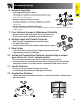
(RS-232C) Using Extended Specifications Functionality and Command Features Settings Multiple and group projector control via computer Building RS-232C 3rd Floor RS-232C Control PC Sharp Advanced Presentation Software “Professional Edition” 2nd Floor RS-232C 1st Floor Video Source 1 Video Source 2 Multiple Function This projector can be used in a network of projectors managed from a single PC with the accompanied Sharp Advanced Presentation Software—Professional Edition.
Using Extended Functionality Features Simultaneous multiple projector control for stacking and videowall projection Multiple Function Stack Projection Master INPUT1 OUTPUT Stack Setting Master Set Inputs INPUT1 Yes INPUT2 Yes INPUT3 No INPUT4 Yes INPUT5 Yes Stack Setting Slave Set Inputs INPUT1 Yes INPUT2 No INPUT3 No INPUT4 Yes INPUT5 Yes INPUT2 INPUT4 INPUT5 RS-232C IN RS-232C OUT Distributor Slave INPUT1 DVD OUTPUT INPUT2 Laser Disc INPUT4 INPUT5 RS-232C IN RS-232C OUT For brighter im
Using Extended Functionality Features Videowall Sharp Advanced Presentation Software “Professional Edition” Control PC RGB SOURCE1 001 RGB SOURCE2 INPUT1 Master 003 Slave OUTPUT INPUT1 OUTPUT INPUT2 INPUT4 INPUT5 INPUT4 RS-232C IN RS-232C OUT INPUT5 RS-232C IN RS-232C OUT Distributor 002 INPUT1 Slave 004 Slave OUTPUT INPUT1 OUTPUT INPUT2 INPUT2 INPUT4 VIDEO SOURCE DVD INPUT5 INPUT4 RS-232C IN RS-232C OUT INPUT5 RS-232C IN RS-232C OUT Slave Set Inputs INPUT1 Yes INPUT2 N
Lamp/Maintenance Indicators Maintenance Indicators POWER indicator LAMP REPLACEMENT indicator Maintenance Indicator TEMPERATURE WARNING indicator TEMPERATURE WARNING indicator Condition The internal temperature is abnormally high. • The warning lights on the projector indicate problems inside the projector. • There are two warning lights: a TEMPERATURE WARNING indicator which warns that the projector is too hot, and a LAMP REPLACEMENT indicator which lets you know when to change the lamp.
Replacing the Lamp CAUTION • Potential hazard of glass particles if lamp ruptures. In case of lamp rupture, contact your nearest Authorized Sharp Industrial LCD Products Dealer or Service Center for a replacement. • Do not remove the lamp cage directly after operation of the projector. The lamp may be extremely hot. Wait at least one hour after the power cord is disconnected to allow the surface of the lamp cage to fully cool before removing the lamp cage.
Replacing the Lamp 7 Remove the lamp cage cover. Turn over the projector and loosen the user service screw that secures the lamp cage cover. Then slide the cover in the direction of the arrow. 8 Remove the lamp cage. Remove the securing screws from the lamp cage. Hold the lamp cage by the handle and pull it towards you. Securing screw 9 Insert the new lamp cage. Press the lamp cage firmly into the lamp cage compartment. Fasten the securing screws.
Replacing the Air Filter • This projector is equipped with two air filters to ensure the optimal operating condition of the projector. • The air filters should be cleaned every 100 hours of use. Clean the filters more often when the projector is used in a dusty or smoky location. • Have your nearest Authorized Sharp Industrial LCD Products Dealer or Service Center exchange the filter (PFILD0080CEZZ) when it is no longer possible to clean it.
Troubleshooting Problem Power cannot be turned on or off using the POWER buttons (ON/OFF) on the projector. Check • Keylock level is set to “Level A” or “Level B”, preventing operation of some or all buttons. (See page 58 .) Cannot be operated by GyroRemote. • Register GyroRemote once again the projector. (See page 37 .) • When the GyroRemote is connected to the projector with wired remote control cable, confirm the position of the IR/Gyro switch. (See page 38 .
Connecting Pin Assignments INPUT 1 RGB and OUTPUT (INPUT 1, 2) Signal Ports: 15-pin Mini D-sub female connector 5 10 15 1 6 11 RGB Input Analog 1. Video input (red) 2. Video input (green/sync on green) 3. Video input (blue) 4. Reserve input 1 5. Composite sync 6. Earth (red) 7. Earth (green/sync on green) Component Input Analog 1. PR (CR) 2. Y 3. PB (CB) 4. Not connected 5. Not connected 6. Earth (PR) 7. Earth (Y) 8. Earth (PB) 8. 9. 10. 11. 12. 13. 14. 15.
(RS-232C) Specifications and Command Settings PC control A computer can be used to control the projector by connecting an RS-232C cable (null modem, cross type, sold separately) to the projector. (See page 16 for connection.) Communication conditions Set the serial port settings of the computer to match that of the table. Signal format: Conforms to RS-232C standard.
(RS-232C) Specifications and Command Settings COMMAND PARAMETER RETURN CONTROL CONTENTS COMMAND PARAMETER RETURN INPUT 1 (RGB 1) SIGNAL TYPE : RGB I A S I _ _ _ 0 OK OR ERR INPUT 1 (RGB 1) RESIZE : FULL R A S R _ _ _ 5 OK OR ERR INPUT 1 (RGB 1) SIGNAL TYPE : COMPONENT I A S I _ _ _ 1 OK OR ERR INPUT 1 (RGB 1) RESIZE : DOT BY DOT R A S R _ _ _ 3 OK OR ERR INPUT 2 (RGB 2) SIGNAL TYPE : RGB I B S I _ _ _ 0 OK OR ERR INPUT 2 (RGB 2) RESIZE : NORMAL R B S R _ _ _ 1 OK OR ERR INPUT 2 (RGB 2) SIGN
(RS-232C) Specifications and Command Settings COMMAND PARAMETER CONTROL CONTENTS RETURN A A B L _ * * * OK OR ERR COMMAND PARAMETER RETURN LAMP USAGE TIME T L T T _ _ _ 1 0–9999 (INTEGER) LAMP STATUS T L P S _ _ _ 1 A A T E _ * * * OK OR ERR A A B A _ * * * OK OR ERR AUDIO DISPLAY A A R E _ _ _ 0 OK OR ERR PRJ MODE : REVERSE OFF I M R E _ _ _ 0 OK OR ERR AUDIO ADJUSTMENT RESET A A R E _ _ _ 1 OK OR ERR PRJ MODE : REVERSE ON I M R E _ _ _ 1 OK OR ERR FAO A O U T _ _ _ 1 OK OR ERR PRJ MOD
Wired Remote Control Terminal Specifications Specifications of wired remote control input • ø3.
Computer Compatibility Chart Horizontal Frequency: 15–126 kHz Vertical Frequency: 43–200 Hz Pixel Clock: 12–230 MHz Compatible with sync on green and composite sync signals UXGA and SXGA compatible in advanced intelligent compression or intelligent compression AICS (Advanced Intelligent Compression and Expansion System) resizing technology PC/ MAC/ WS Resolution 640 720 640 720 350 350 400 400 VGA 640 480 PC SVGA XGA 800 1,024 600 768 Horizontal Frequency (kHz) Vertical Frequency (Hz)
Dimensions Rear View Side View Top View 11 3/25 (282.5) 6 3/32 (155) 12 9/16 (319) 9 32 / (7) 1 8 / (3) 17 15/64 (438) 16 21/32 (423) 3 1/6 (79) Side View 9 /64 (3.5) 29 32 / (23) 4 37/64 (116.5) 2 9/16 (65) Front View 1 3/64 (26.
Specifications Product type LCD Projector Model XG-P20XU Video system PAL/PAL 60/PAL-M/PAL-N/SECAM/NTSC 3.58/NTSC 4.43 DTV 480P/720P/1080i Display method LCD panel 3, RGB optical shutter method LCD panel Panel size: 1.3 (20.0 [H] 26.6 [W] mm) Display method: Translucent TN liquid crystal panel Drive method: TFT (Thin Film Transistor) Active Matrix panel No. of dots: 786,432 dots (1,024 [H] 768 [V]) Standard Lens 1–1.3 zoom lens, F1.7–2.3, f = 49.1–63.
Glossary Aspect ratio Width and height ratio of an image. The normal aspect ratio of a computer and video image is 4:3. There are also wide images with an aspect ratio of 16:9 and 21:9. Auto Sync Optimizes projected computer images by automatically adjusting certain characteristics. Background Initial setting image projected when no signal is being input. Border Displays the 4:3 image as the biggest size (768 576) that can be displayed on the WIDE mode screen (1024 576).
Index A AC socket ........................................................................ Adjusting the Picture ....................................................... Adjustment Feet .............................................................. Air filter ............................................................................ Aspect ratio ..................................................................... ASSIGN Select button ..................................................... Audio ............
SHARP CORPORATION