R- 360EG R - 3 60 E S R-360EW R- 360EZ SERVICE MANUAL S3107R360EPW/ MICROWAVE OVEN MODELS Popcorn Baked Potatoes Vegetables Rolls & Muffins Dinner Plate Frozen Entrees Compu Defost Instant Action Ground Meat Chicken Breast Casserole Beverage MIcrowave Pizza Kitchen Timer Clock NO. LBS.
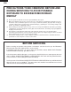
R-360EG R- 360ES R-360EW R- 360EZ PRECAUTIONS TO BE OBSERVED BEFORE AND DURING SERVICING TO AVOID POSSIBLE EXPOSURE TO EXCESSIVE MICROWAVE ENERGY (a) Do not operate or allow the oven to be operated with the door open.
R-360EG R-360ES R-360EW R- 360EZ WARNING TO SERVICE PERSONNEL Microwave ovens contain circuitry capable of producing very high voltage and current, contact with following parts may result in a severe, possibly fatal, electrical shock. (Example) High Voltage Capacitor, High Voltage Power Transformer, Magnetron, High Voltage Rectifier Assembly, High Voltage Harness etc.. Read the Service Manual carefully and follow all instructions. Don't Touch ! Danger High Voltage When the testing is completed, 1.
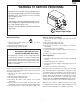
MICROWAVE MEASUREMENT PROCEDURE A. Requirements: 1) Microwave leakage limit (Power density limit): The power density of microwave radiation emitted by a microwave oven should not exceed 1mW/cm2 at any point 5cm or more from the external surface of the oven, measured prior to acquisition by a purchaser, and thereafter (through the useful life of the oven), 5 mW/cm2 at any point 5cm or more from the external surface of the oven.
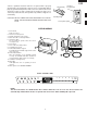
R-360EG R-360ES R-360EW R- 360EZ SERVICE MANUAL PRODUCT DESCRIPTION MICROWAVE OVEN R-360EG/ R-360ES/ R-360EW/ R-360EZ GENERAL INFORMATION FOREWORD This Manual has been prepared to provide Sharp Electronics Corp. Service Personnel with Operation and Service Information for the SHARP MICROWAVE OVEN, R-360EG, R-360ES, R-360EW, R360EZ. OPERATION It is recommended that service personnel carefully study the entire text of this manual so that they will be qualified to render satisfactory customer service.
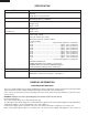
SPECIFICATION ITEM DESCRIPTION Power Requirements 120 Volts / 13.5 Amperes 60 Hertz Single phase, 3 wire grounded Power Output 1000 watts (IEC TEST PROCEDURE) Operating frequency of 2450MHz Case Dimensions Width 16-7/8" Height 13-3/8" Depth 18-3/4" Cooking Cavity Dimensions Width 13-3/4" Height 7-1/4" Depth 16-1/2" 1.4 Cubic Feet Control Complement Touch Control System Clock ( 1:00 - 12:59 ) Timer (0 - 99 min. 99 seconds) Microwave Power for Variable Cooking Repetition Rate; P-HI ................
R-360EG R-360ES R-360EW R- 360EZ contact a qualified electrician and have it replaced with a properly grounded three-pronged wall receptacle or have a grounding adapter properly grounded and polarized. If the extension cord must be used, it should be a 3-wire, 15 amp. or higher rated cord. Do not drape over a countertop or table where it can be pulled on by children or tripped over accidentally. CAUTION: DO NOT UNDER ANY CIRCUMSTANCES CUT OR REMOVE THE ROUND GROUNDING PRONG FROM THIS PLUG.
OPERATION DESCRIPTION OF OPERATING SEQUENCE The following is a description of component functions during oven operation. relay (RY2) and is mechanically associated with the door so that it will function in the following sequence. (1) When the door opens from the closed position, the secondary interlock relay (RY2) and primary interlock switch open their contacts. And contacts of the relay (RY1) remains closed. Then the monitor switch contacts close.
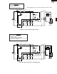
R-360EG R-360ES R-360EW R- 360EZ SCHEMATIC NOTE: CONDITION OF OVEN 1. DOOR CLOSED 2. CLOCK APPEARS ON DISPLAY MONITOR FUSE 20A NOTE: " " indicates components with potential above 250V. OVEN THERMAL CUT-OUT MG. THERMAL CUT-OUT POWER TRANSFORMER N.O. SECONDARY INTERLOCK RELAY (RY2) CAPACITOR 0.94µF AC 2200V COM. GRN B2 120V AC 60 Hz B1 MONITOR SWITCH CONTROL UNIT DOOR SENSING SWITCH OL OVEN LAMP RELAY (RY1) N.O.
DESCRIPTION AND FUNCTION OF COMPONENTS DOOR OPEN MECHANISM CAUTION: BEFORE REPLACING A BLOWN MONITOR FUSE TEST THE DOOR SENSING SWITCH, SECONDARY INTERLOCK RELAY (RY2), RELAY (RY1), PRIMARY INTERLOCK SWITCH AND MONITOR SWITCH FOR PROPER OPERATION. (REFER TO CHAPTER "TEST PROCEDURE"). NOTE: MONITOR FUSE AND MONITOR SWITCH ARE REPLACED AS AN ASSEMBLY. The door is opened by pulling the door. Refer to the Figure D-1.
R-360EG R-360ES R-360EW R- 360EZ TROUBLESHOOTING GUIDE Never touch any part in the circuit with your hand or an uninsulated tool while the power supply is connected. When troubleshooting the microwave oven, it is helpful to follow the Sequence of Operation in performing the checks. Many of the possible causes of trouble will require that a specific test be performed. These tests are given a procedure letter which will be found in the "Test Procedure "section.
CK = Check / RE = Replace Home fuse or circuit breaker blows when power cord is plugged into wall receptacle. Monitor fuse blows when power cord is plugged into wall receptacle. OFF CONDITION Any letters or indicators do not appear in display when power cord is first plugged into wall outlet. Display does not operate properly when STOP/CLEAR key is touched. (Buzzer should sound and ":" or time of day should appear in display.) Oven lamp does not light when door is opened.
R-360EG R-360ES R-360EW R- 360EZ TEST PROCEDURES PROCEDURE LETTER COMPONENT TEST 4. To test for an open filament, isolate the magnetron from the high voltage circuit. A continuity check across the magnetron filament leads should indicate less than 1 ohm. 5. To test for a shorted magnetron, connect the ohmmeter leads between the magnetron filament leads and chassis ground. This test should indicate an infinite resistance. If there is little or no resistance the magnetron is grounded and must be replaced.
TEST PROCEDURES PROCEDURE LETTER C COMPONENT TEST HIGH VOLTAGE RECTIFIER TEST 1. 2. 3. 4. Disconnect the power supply cord, and then remove outer case. Open the door and block it open. Discharge the high voltage capacitor. Isolate the rectifier from the circuit. Using the highest ohm scale of the meter, read the resistance across the terminals and observe, reverse the leads to the rectifier terminals and observe meter reading.
R-360EG R-360ES R-360EW R- 360EZ TEST PROCEDURES PROCEDURE LETTER COMPONENT TEST CAUTION: IF THE THERMAL CUT-OUT INDICATES AN OPEN CIRCUIT AT ROOM TEMPERATURE, REPLACE THERMAL CUT-OUT. F PRIMARY INTERLOCK SWITCH TEST 1. 2. 3. 4. 5. 6. 7. 8. Disconnect the power supply cord, and then remove outer case. Open the door and block it open. To discharge the high voltage capacitor, wait for 60 seconds. Isolate the switch and connect the ohmmeter to the common (COM.
TEST PROCEDURES PROCEDURE LETTER COMPONENT TEST 5. 6. 7. 8. Reconnect all leads removed from components during testing. Reinstall the outer case (cabinet). Reconnect the power supply cord after the outer case is installed. Run the oven and check all WHT functions. RED Screw Driver Monitor Switch Primary Interlock Switch H Ohmmeter BLOWN MONITOR FUSE TEST 1. 2. 3. 4. Disconnect the power supply cord, and then remove outer case. Open the door and block it open.
R-360EG R-360ES R-360EW R- 360EZ TEST PROCEDURES PROCEDURE LETTER COMPONENT TEST 2-1 In connection with pads. a) When touching the pads, a certain group of pads do not produce a signal. b) When touching the pads, no pads produce a signal. 2-2 In connection with indicators a) At a certain digit, all or some segments do not light up. b) At a certain digit, brightness is low. c) Only one indicator does not light. d) The corresponding segments of all digits do not light up; or they continue to light up.
TEST PROCEDURES PROCEDURE LETTER K COMPONENT TEST RELAY TEST 1. 2. 3. 4. 5. Disconnect the power supply cord, and then remove outer case. Open the door and block it open. To discharge the high voltage capacitor, wait for 60 seconds. Disconnect the leads to the primary of the power transformer. Ensure that these leads remain isolated from other components and oven chassis by using insulation tape. 6. After that procedure, re-connect the power supply cord. 7.
R-360EG R-360ES R-360EW R- 360EZ TEST PROCEDURES PROCEDURE LETTER COMPONENT TEST OCCURRENCE CAUSE OR CORRECTION Only pattern at "a" is broken. *Insert jumper wire J1 and solder. 2 Pattern at "a" and "b" are broken. *Insert the coil RCILF2003YAZZ between "c" and "d". RY2 a d (J1) 5) Make a visual inspection of the varistor.
TOUCH CONTROL PANEL ASSEMBLY OUTLINE OF TOUCH CONTROL PANEL 3) Power Source Circuit This circuit generates voltages necessary in the control unit from the AC line voltage. In addition, the synchronizing signal is available in order to compose a basic standard time in the clock circuit. The control unit section consists of the following units. (1) Key Unit (2) Control Unit (The Control Unit consists of Power Unit and CPU Unit).
R-360EG R-360ES R-360EW R- 360EZ Pin No. Signal I/O Description 11-13 P57-P55 OUT Terminal not used. 14 CNTR0 OUT Signal to sound buzzer (2.0 kHz). A: key touch sound. B: Completion sound. 0.1 sec. H : GND A L : -5V 2.0 sec. H : GND B L : -5V 15 P53 OUT Terminal not used. 16 P52 OUT Oven lamp, fan motor and turntable motor driving signal 16.7 msec. To turn on and off shut off relay (RY1). The square waveform voltage is delivered to the RY1 driving circuit and RY2 control circuit.
Pin No. Signal I/O Description 32 VSS IN 33 P27 OUT Terminal not used. 34 P26 OUT Key strobe signal. Signal applied to touch-key section. A pulse signal is input to P43-P46 terminal while one of G7 line keys on key matrix is touched. 35 P25 OUT Key strobe signal. Signal applied to touch-key section. A pulse signal is input to P43-P46 terminal while one of G6 line keys on key matrix is touched. 36 P24 OUT Key strobe signal. Signal applied to touch-key section.
R-360EG R-360ES R-360EW R- 360EZ TOUCH CONTROL PANEL SERVICING transformer. 4) Re-install the outer case (cabinet). 5) Re-connect the power supply cord after the outer case is installed. 6) Run the oven and check all functions. A. On some models, the power supply cord between the touch control panel and the oven itself is so short that the two can’t be separated.
COMPONENT REPLACEMENT AND ADJUSTMENT PROCEDURE WARNING AGAINST HIGH VOLTAGE: Microwave ovens contain circuitry capable of producing very high voltage and current, contact with following parts may result in severe, possibly fatal, electric shock. (Example) High Voltage Capacitor, Power Transformer, Magnetron, High Voltage Rectifier Assembly, High Voltage Harness etc.. WARNING: Avoid possible exposure to microwave energy. Please follow the instructions below before operating the oven. 1.
R-360EG R-360ES R-360EW R- 360EZ 6. Lift entire outer case from the unit. CAUTION: 1. DISCONNECT OVEN FROM POWER SUP PLY BEFORE REMOVING OUTER CASE. 2. DISCHARGE THE HIGH VOLTAGE CAPACITOR BEFORE TOUCHING ANY OVEN COMPONENTS OR WIRING. NOTE: When replacing the outer case, the 2 special Torx screws must be reinstalled in the same locations.
transformer from the high voltage capacitor. 6. Remove one (1) screw holding capacitor holder to base plate. 7. Remove one (1) screw holding high voltage rectifier assembly to capacitor holder. 8. Disconnect rectifier terminal from the capacitor. High voltage rectifier assembly is now free. 9. Remove the capacitor holder. The capacitor is now free.
R-360EG R-360ES R-360EW R- 360EZ 5. Install the fan blade to the shaft of fan motor by pushing the fan blade with a small, light weight, ball peen hammer or rubber mallet. CAUTION: * Do not hit the fan blade strongly when installed because the bracket may be disfigured. * Make sure that the fan blade rotates smooth after installation. * Make sure that the axis of the shaft is not slanted. 6. Catch two holes of fan duct on two tabs of the base plate. 7.
DOOR SENSING SWITCH/PRIMARY INTERLOCK SWITCH AND MONITOR SWITCH REMOVAL Reinstallation 1. Re-install each switch in its place. The primary interlock/ monitor switches are in the lower position and the door sensing switch is in the upper position. 2. Re-connect wire leads to each switch. Refer to pictorial diagram. 3. Make sure that the monitor switch is operating properly and check continuity of the monitor circuit. Refer to chapter "Test Procedure" and Adjustment procedure. 1.
R-360EG R-360ES R-360EW R- 360EZ NOTE: When carrying out any repair to the door, do not bend or warp the slit choke (tabs on the door panelassembly) to prevent microwave leakage. 11.Release two (2) pins of door panel from two (2) holes of upper and lower oven hinges by lifting up. 12.With pulling out the 7-pin wire harness from the hole of the oven cavity front plate and the front cover. Remove the door from the oven cavity. 13.Now, the door is free from the oven cavity.
CPU UNIT 7. Remove the two (2) screws holding the PWB cover to the door frame assembly. 8. Remove the PWB cover from the door frame assembly. 9. Remove the one (1) screw holding the CPU unit to the door frame assembly. 10.Releasing the two (2) tabs, remove the CPU unit with the LCD holder from the door frame assembly. 11.Releasing the two (2) tabs, release the LCD from the LCD holder. 12.Releasing the four (4) tabs, remove the LCD holder from the CPU unit. 13.
1 2 3 29 4 5 PPL 7 BLU 6 GRN 5 ORG 3 YLW 4 7 1 3 CN-C 1 CN-B WHT GRY CN-B 1 GRN 2 3 GRY BLK MONITOR FUSE & HOLDER BLK 6 B L U 5 G R N 9 4 3 2 Y O R L R E W G D CN-C 1 IC1 1 B R N RED BLK WHT WHT N.C. 6 COM. WHT WHT WHT GRY GRN GRY WHT COM. PRIMARY NO INTERLOCK SWITCH MONITOR SWITCH RED FAN MOTOR N.O. BLK ORG RED THERMAL CUT-OUT (MG) OVEN LAMP 5 Figure S-1.
2 1 4 3 6 5 A A B B D1-D4 1N4002 T1 1 7 D4 D2 + C C2 VR C3 INT C4 OVEN LAMP TURNTABLE MOTOR FAN MOTOR C6 BUZZER c (J1) – GND C2 1000µ/25v 4 C1 0.1µ/50v 3 b a C CN-C D1 C1 d VRS1 10G471K D3 – OVEN LAMP TURNTABLE MOTOR FAN MOTOR AC(H) NO D21 1SS270A AC(N) COM RY1 NO E MICRO COM D Q21 DTD143ES SP1 PKM22EPT D22 1SS270A D + C21 10µ/35v E R4 3.
C7 DOOR SENSING SWITCH NOTE C5 C4 C6 C3 C2 MICRO OVEN LAMP TURNTABLE MOTOR FAN MOTOR BUZZER INT VA R9 560 1/2w LD1 LD2 LD3 LD4 R40 4.7k C1 0.1µ/50v C20 0.1µ/50v R20 1k R3 4.7k Q1 2SA1037AK : IF NOT SPECIFIED, 1/16W ± 5% R41 15k Q20 DTA143EKA Q30 DTA143EKA Q10 DTA143EKA C1 0.1µ /50v – + R4 1k ZD1 UDZ4.3B R1 82 R10 15k C4 0.01µ/25v (J12) 3.6k (J13) 4.7k (J10) (J11) 4.
2 4 6 A B C2 C21 B C 1 SP1 R4 1 B CN-C CN-B 2 7 1 A 5 D40 3 D20 1 C E Q22 E 2 D1 D3 C1 T1 B Q21 D S P 1 7 D E RY1 D2 D21 4 3 D4 E F VRS1 F G D22 RY2 G (J1) H H Figure S-4.
R- 360EG R - 3 60 E S R-360EW R- 360EZ PARTS LIST Note: The parts marked “∆” may cause undue microwave exposure. The parts marked “*” are used in voltage more than 250V. REF. NO. PART NO.
R- 360EG R-360ES R-360EW R- 360EZ ∆ ∆ ∆ ∆ ∆ ∆ REF. NO. 4-22 4-23 4-24 4-25 4-26 4-27 4-28 PART NO.
R- 360EG R - 3 60 E S R-360EW R- 360EZ 2 1 4 3 6 5 OVEN AND CABINET PARTS 7-13 4-17 2-4 A A 7-14 7-4 4-18 7-8 4-26 B B 6-6 1-13 4-25 4-24 1-1 4-28 4-27 7-14 7-12 4-19 C C 6-5 7-13 4-6 7-7 7-11 4-21 1-9 4-23 7-11 D D 4-9 7-9 7-15 7-3 4-22 4-16 1-4 7-7 4-11 7-1 7-2 4-15 1-12 E 7-1 7-11 4-5 4-4 4-4 x2 E 1-11 2-2 7-1 4-8 1-3 4-1 7-11 7-1 x2 7-7 1-8 1-5 7-5 4-3 1-2 1-8 7-3 4-12 1-4 F 4-14 4-20 1-3 7-11 7-5 F 7-10 7-6 7-3 7-7 1-10 6-2 4-2 7-1
R- 360EG R-360ES R-360EW R- 360EZ 2 1 4 3 6 5 A A DOOR PARTS 5-10 5-13 5-11 5-9 5-13 5-12 4-7 5-6 5-7 B 5-2 B 5-12 5-14 5-6 5-8 5-1 5-12 5-3 C C 5-12 5-3-1 5-4 D D 5-3-2 5-5 MISCELLANEOUS E E 6-3 6-8 6-4 (CAPACITOR) F F 6-9 Actual wire harness may be different from illustration.
R- 360EG R - 3 60 E S R-360EW R- 360EZ PACKING AND ACCESSORIES TOP PAD ASSEMBLY DOOR PROTECTION SHEET FPADBA451WRKZ SPADPA204WRE0 WRAP COVER SSAKHA072WREZ CABINET COVER FORM SHEET SPAKHA018WREZ SPAKHA017WREZ 6- 7 INSTRUCTION BOOK & PRINTING MATTER BOTTOM PAD ASSEMBLY 6- 2 TURNTABLE TRAY FPADBA452WRKZ 6- 1 TURNTABLE SUPPORT TRAY PAD INTO THE OVEN CAVITY SPADFA499WREZ Not replaceable items.
R- 360EG R-360ES R-360EW R- 360EZ COPYRIGHT © 2001 BY SHARP CORPORATION ALL RIGHTS RESERVED. No part of this publication may be reproduced, stored in retrieval systems, or transmitted in any form or by any means, electronic, mechanical, photocopying, recording, or otherwise, without prior written permission of the publisher. 2001 SHARP CORP. (3S2.530E) Printed in U.S.