
System information


www.turnerbiosystems.com 3
1.1.3 Unpacking and Inspection
Upon receiving the Modulus™ Microplate Reader, inspect it carefully for any damage to
the exterior such as scratches and/or dents. Make certain all accessories are included.
Refer to the checklist shipped with the instrument for order-specific items. Save all
packaging materials, if possible, in case the instrument needs to be shipped to a service
center in the future.
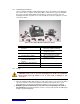
#
Content
#
Content
1
Modulus
™
Microplate Reader
Instrument
7
Non-Sterilized 96-Well
Microplates (optional starter kit)
2
Power Line Cord
8
Waste Collection Tray (included
with injector system)
3
Power Supply Brick, 24V, 60W
9
Outlet Injector Tube Assembly
(included with injector system)
4
USB Flash Drive, 264MB
10
DB-15 Serial Cable (included
with injector system)
5
Fluorescence Optical Kits
(included with fluorescence
module)
11
Injector System (optional)
6
Luminescence Standard Light
Plate (optional)
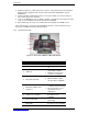
1.1.4 Set Up
CAUTION: Remove all of the foam packaging from inside the instrument
before initial power up. Failure to do so may result in damage to the
electronics.
1. Place the Modulus™ Microplate Reader on a flat, level surface. Leave at least 7.5 inches
(19 cm) of clearance in front of the instrument to allow the instrument door to open
without hindrance. Position the instrument so that the touch screen faces outward.
2. Manually open the instrument door and remove the foam packing from inside of
the instrument. The packing material is used to secure the optical heads and Microplate
Sample Tray during shipping.
1
2
3
4
5
6
7
9
8
10
11
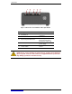
Figure 1-1: A Complete Modulus™ Microplate System