TECHNICAL MANUAL (ver.2.
Contents Features .................................................................................................................................................................. 4 specifications .......................................................................................................................................................... 6 2.1 List of specifications ..................................................................................................................................
Contents 4.8.3 Assembling and installing the metal fixture and mounting the plasma display ................................... 95 4.9 PDP bracket: PDK-4005 .............................................................................................................................. 98 4.9.1 Specifications ....................................................................................................................................... 98 4.9.
Features Features and functions of the plasma display (PDP-V402/V402E) ¶ Layout Freedom and Slim Design Layout freedom is enhanced by providing the highest level of thinness and lightness in the industry (Thinness: 88 mm, Weight: 30.8 kg). The thin, light form of the plasma display panel provides immediate improvement of operating conditions by increasing the potential installation locations and style coordination for smooth integration into a variety of applications.
Features 5
List of specifications 2.1 List of specifications Light emission panel ...... 40-inch plasma display panel Aspect ratio ............................................................. 4:3 No. of pixels ................... 640 × 480 (adaptable to VGA) Pixel pitch ........... 1.26 (horizontal, RGB trio) × 1.26 (vertical) mm No. of gradations ................................ 256 gradations/ 16,770,000-color full color View angle ............................
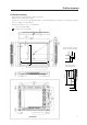
Outline drawing 2.2 Outline drawing Plasma display main body weight : 30.8 kg <31.6 kg> Material : Front - Plastic, Back - plate Treatment : Front - Leather satin gray paint, Back - Semi-matte black paint (Coating colors should be according to Pioneer's original color specification) Packing specifications - See “3.3.2 Unpacking” • < > shows the PDP-V402E. 604.8 (Effective picture size) : Location of center of gravity 24 806.
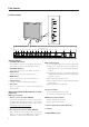
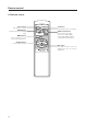
Part names 2.3 Part names STANDBY /ON 1 2 INPUT 3 MENU 4 ADJUST 5 SET 6 (The terminals and power supply section are located at the back of the plasma display main body.) 7 OFF 8 ON REMOTE 9 0 OFF RGB-2 ON 75 (Ω) 2.
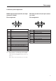
Part names 2.4 Various pin arrangements RGB-2 input terminal (mini D-sub 15-pin connector: female) Pin arrangement 5 1 10 1 5 6 15 Pin No. RS-232C terminal (D-sub 9-pin connector: male) Pin arrangement 11 Signal 6 Pin No.
Remote control 2.5 Remote control Power button Turns power on or off. VIDEO button Sets Input Function to VIDEO Input. MENU button Used to switch the menu screen and normal screen. ADJUST button Used to adjust images. STANDBY/ON VIDEO Y/C INPUT SELECT RGB 1 RGB 2 MENU RGB 1 and 2 buttons These buttons set Input Functions to RGB 1 (BNC terminal) and RGB 2 (Mini DSUB terminal), respectively. SET Î 10 Y/C button Sets Input Function to Y/C input.
Remote control 2.6 Remote control case Remove the peel-off paper from the double-sided tape on the back of the remote control case, and attach it on the back of this display or on the installation metal fixture to use as a remote control storage case. Remote Example of attaching a remote control case Remote control case Double-sided tape (Note) Make sure not to block any air inlet hole with the remote control case.
Installation environment 3.1 Installation environment The plasma display and special metal fixture must be installed after careful discussion with the building owner and manager of the building. Never undertake installation without careful consideration of the consequences. In addition, contact the contractor responsible for building construction and interior structure design and confirm the structure and safety of the building.
Installation environment 9) Temperature and humidity The installation site should conform to the following temperature and humidity conditions: • Operating temperature range: 0 to 40 °C (Depending somewhat on installation conditions, see descriptions of special installations and methods for installation of the standard metal fixture.) Operating environment humidity range .............. Relative humidity 20% to 80% Operating environment air pressure range ......... 0.8 - 1.
Installation conditions 3.2 Installation conditions 3.2.1 Radiation This display comes with multiple ventilation holes for efficient radiation of heat. Avoid blocking any of these holes. Ventilation holes are indicated by arrows in the following drawing. 2 ø6 49.8 mm 539 mm (Size of air inlet hole) 463 mm (Size of air inlet hole) 377 mm (Size of air inlet hole) 49 mm (Size of air inlet hole) 328 (Size of air inlet hole) 638 (Size of air inlet hole) 49.
Installation conditions 3.2.3 Installation position We recommend using the metal installation fixture made by Pioneer. When using a different fixture, use the M8 bolt hole provided on this display to mount the fixture to the display. Remove the hole rivets on the back of the plasma display, if necessary for the particular fixture. Tighten bolts with a force of 60 kg.cm or less. Overtightening may damage the blind nuts. • The following figure indicates mounting holes that can be used.
Installation conditions We recommend mounting at a minimum of 4 points, and at 6 or 8 points as shown below if possible. Avoid mounting the display with the particular 4-point scheme shown below. Mounting method — bad example Mounting method — good example A. 8-point mounting B. 6-point mounting (Do not block ventilation holes.) C. 4-point mounting (Metal fixture is mounted vertically.) (Do not block ventilation holes.) D. 4-point mounting (Metal fixture is mounted horizontally.
Installation conditions 3.2.4 Strain on surface where equipment is installed 1 This display uses glass in its display section. When using a third-party metal fixture, check that strain is 1 mm or less by the following method. 2 Tightly fit a thread using a force of φ 0.1psi or less diagonally through the mounting bolt openings on the mounting surface, as shown in the drawing. 3 Measure distance L of the intersection of the strings in the center section.
Installation procedure 3.3 Installation procedure 3.3.1 Precautions for transportation 1 Use two workers to move packages. Do not grasp the PP band during transportation. The band may snap and result in injury. 2 For transportation and storage, keep the package horizontal. Do not stack packages longitudinally or laterally. If packages are transported or stored while longitudinally stacked or laterally stacked, the company is guarantee will be invalidated.
Installation procedure 2) Procedure for unpacking 1 Remove the PP band. 2 Slowly lift and remove the upper carton. 3 Remove the catalogue bag (9) (instruction manuals), stand (19), and the plastic bag for (26) (accessories) on top of the upper pad. Caution: If the upper pad (4) is removed before removing these items, the items may fall and damage the product. 4 Remove the upper pad (4). 5 Open the mirror mat (8). 6 Remove the product. (Requires two workers to remove the set.
Installation procedure 3.3.3 Wiring 1) Power source connection • Refer to Power cord connection on page 24 <36, 82> of the instruction manual. • For power source capacity, see the description given in “3.1 Installation environment, 11) Power requirements” in this manual. 2) Signal cable connection (1) Connecting to a PC • See the description given in Connecting to a PC , on pp. 19 to 20 <26 to 29, 72 to 75> of the instruction manual.
Installation procedure 21
Installation conditions Outline of conditions for installing PDP-V402 system For installation space (distances from surrounding structures and so forth), make sure to carefully read this section. Installation conditions Room VIDEO Page temperatures PC-9800 70.1Hz 72.
Installation conditions Installation conditions Wall embedding (less than 60 mm) Vertical installation with rear open Room VIDEO Page temperatures P42 air *2 Wall embedding (less than 150 mm) Vertical installation with rear open air *2 Wall embedding Vertical installation with front mesh PC-9800 56.4Hz Machintosh 66.7Hz VGA 60Hz PC-9800 70.1Hz 72.
Special installations (Fixing on a structure) 3.4 Special installations This display may be installed in several different positions, including wall-hanging and wall-embedding. Conditions, including temperature, may restrict the use of certain positions or installation methods. Consider installation methods and conditions, and see the description given in “3.1 to 3.3” in this chapter. All the measurement conditions in this manual are set in conformity with the following: • 100% white light is applied.
Special installations (Fixing on a structure) Example 1: Example 2: When normally installed Beams Example 1, 2 Beams VIDEO PC-9800 (56.4Hz) Machintosh(66.7Hz) 0~40°C VGA (60Hz) 0~40°C PC-9800 (70.1Hz) VGA (72.8Hz, 75Hz) 0~40°C * The same conditions apply to the working temperature requirements for a speaker system (PDP-S03-LR). *When mounting the down converter (PDA-4003), the same working temperature conditions apply.
Special installations (Wall hanging) 3.4.2 Wall hanging This display may be wall-mounted. Since this form of mounting affects ventilation patterns inside, observe the following requirements: 1 When mounting plate metal, avoid blocking any ventilation holes. Use plate metal of the size indicated in the following drawing. 2 Provide space for adequate ventilation between the wall and the display.
Special installations (Wall hanging) Securing method: Basically, the unit is secured as indicated below. Keep open all areas other than the shaded parts. The fixing method marked cannot be used for the unit. When the unit is fixed on a structure, select a structure of the proper thickness and height. Care must also be taken regarding the number of fixing bolts to be used (see “3.4.1 Fixing on a structure”).
Special installation (Wall hanging) A B 50mm B Do not block this area at either the left or right. 10mm Basically, it is not recommended to operate this display in any confined space. In the event that you are going to use this display in a closed space, make sure to observe the following requirements in accordance with the above drawing. B ≥ 100mm * No limitations of upper and lower clearances for the plasma display Working temperature requirements Clearance A to the wall VIDEO PC-9800 (56.
Special installations (Wall hanging) Securing method: Basically, the unit is secured as indicated below. Keep open all areas other than the shaded parts. The fixing method marked cannot be used for the unit. When the unit is fixed on a structure, select a structure of the proper thickness and height. Care must also be taken regarding the number of fixing bolts to be used (see “3.4.1 Fixing on a structure”).
Special installations (Wall embedding) 3.4.3 Wall embedding This display is designed to accommodate embedding in a wall. Note that the allowable range of outside-air temperature depends on the installation conditions. Please observe the following requirements: 1 Use a metal mounting fixture that does not block the side slits or the back ventilation holes, and attach at a minimum of four points. To avoid breaking the PDP panel, limit any twisting or bending stress applied to the display to 1 mm or less.
Special installations (Wall embedding) Securing method: Basically, the unit is secured as indicated below. Keep open all areas other than the shaded parts. The fixing method marked cannot be used for the unit. When the unit is fixed on a structure, select a structure of the proper thickness and height. Care must also be taken regarding the number of fixing bolts to be used (see “3.4.1 Fixing on a structure”).
Special installations (Wall embedding) 50mm or more Y Punching net X 100mm or more 100mm or more 100mm or more 50mm 10mm Aperture efficiency 50% or more 100mm or more Working temperature requirements VIDEO PC-9800 (56.4Hz) Machintosh (66.7Hz) 0~40°C VGA (60Hz) 0~40°C PC-9800 (70.1Hz) VGA (72.8Hz, 75Hz) 0~35°C * When mounting the down converter (PDA-4003), the same working temperature conditions apply.
Special installations (Wall embedding) Securing method: Basically, the unit is secured as indicated below. Keep open all areas other than the shaded parts. The fixing method marked cannot be used for the unit. When the unit is fixed on a structure, select a structure of the proper thickness and height. Care must also be taken regarding the number of fixing bolts to be used (see “3.4.1 Fixing on a structure”).
Special installation (Putting in a box) Rear side mesh 3.4.4 When the display is put in a box Operating this display in confined spaces is not recommended. • If the display is to be used in confined spaces, observe the following conditions shown in the drawing in a page to the right: A ≥ 50 B ≥ 50 C ≥ 10 D ≥ 50 Use a mesh with aperture efficiency of 50% or more. • Keep the temperature in the closed space "Y" and the open space "X" less than the following temperature range.
Special installation (Putting in a box) Rear side mesh Mesh Mesh Intake side Outside air temperature measuring point 10mm Exhaust side A A B 10mm B D C B+50mm B+50mm Rear view (the following area should be made of mesh) Mesh with aperture efficiency of 50% or more 614mm 614mm Area 900 cm2 or more B+50mm B+50mm Minimum area 900 cm2 or more A ≥ 50 B ≥ 50 C ≥ 10 D ≥ 50 A+50mm 150mm or more 150mm or more A+50mm 35
Special installation (Putting in a box) Mesh (side) Operating this display in confined spaces is not recommended. • If the display is to be used in confined spaces, observe the following conditions shown in the drawing in a page to the right: A ≥ 50 B ≥ 50 C ≥ 10 D ≥ 50 Use a mesh with aperture efficiency of 50% or more. • Keep the temperature in the closed space "Y" and the open space "X" less than the following temperature range.
Special installation (Putting in a box) Mesh (side) Intake side Mesh Exhaust side 100 mm Mesh Outside air temperature measuring point A A B 10mm B C B+50 mm B+50 mm D 564 mm 564 mm Minimum area 500 cm2 or more A ≥ 50 B ≥ 50 C ≥ 10 D ≥ 50 B+100 mm 100 mm C or more (Intake side) B+100 mm Mesh with aperture efficiency of 50% or more 100 mm or more (Exhaust side) C 37
Special installation (Wall hanging (vertically wall-hanging equipment)) 3.4.5 Wall hanging (vertically wall-hanging equipment) This display is designed to accommodate a range of wall installations. For this type of installation, carefully consider all installation specifics before beginning work, since these factors can significantly affect the temperature of the air surrounding the display.
Special installation (Wall hanging (vertically wall-hanging equipment)) Securing method: Basically, the unit is secured as indicated below. Keep open all areas other than the shaded parts. The fixing method marked cannot be used for the unit. When the unit is fixed on a structure, select a structure of the proper thickness and height. Care must also be taken regarding the number of fixing bolts to be used (see “3.4.1 Fixing on a structure”).
Special installation (Wall hanging (vertically wall-hanging equipment)) B 50mm A B C 50mm C Basically, it is not recommended to operate this display in any confined space. In the event that you are going to use this display in a closed space, make sure to observe the following requirements in accordance with the above drawing. B ≥ 100mm C ≥ 100mm Working temperature requirements Clearance A to the wall VIDEO PC-9800 (56.4Hz) Machintosh (66.
Special installation (Wall hanging (vertically wall-hanging equipment)) Securing method: Basically, the unit is secured as indicated below. Keep open all areas other than the shaded parts. The fixing method marked cannot be used for the unit. When the unit is fixed on a structure, select a structure of the proper thickness and height. Care must also be taken regarding the number of fixing bolts to be used (see “3.4.1 Fixing on a structure”).
Special installation (Wall embedding (vertically wall-embedding equipment)) 3.4.6 Wall embedding (vertically wall-embedding equipment) This display is designed to accommodate embedding in a wall. Since the allowable range of outside-air temperature depends on the installation conditions. Please observe the following conditions: 1 Use a metal mounting fixture that does not block the side slits or the back ventilation holes, and attach at a minimum of four points.
Special installation (Wall hanging (vertically wall-hanging equipment)) Securing method: Basically, the unit is secured as indicated below. Keep open all areas other than the shaded parts. The fixing method marked cannot be used for the unit. When the unit is fixed on a structure, select a structure of the proper thickness and height. Care must also be taken regarding the number of fixing bolts to be used (see “3.4.1 Fixing on a structure”).
Special installations (Wall hanging (Vertically installing this display by embedding in the wall) (2) When there is a closed space behind the wall. Punching net B A Punching net 50mm 50mm B Aperture ratio 50% or more C Punching net C Punching net B ≥ 100 C ≥ 100 Basically, it is not recommended to operate this display in a confined space. In the event that you are going to use this display in a closed space, make sure to observe the following requirements in accordance with the above drawing.
Special installation (Wall hanging (vertically wall-hanging equipment)) Securing method: Basically, the unit is secured as indicated below. Keep open all areas other than the shaded parts. The fixing method marked cannot be used for the unit. When the unit is fixed on a structure, select a structure of the proper thickness and height. Care must also be taken regarding the number of fixing bolts to be used (see “3.4.1 Fixing on a structure”).
Special installation (Ceiling suspension (using wires)) 3.4.7 Ceiling suspension (using wires) Mount the display with the fans on the upper side. C C A B B A D D When suspending the display by wires, use a combination of two mounting rows, as shown in the diagram above (rows A - B or C - D, from rows A - D). This is done to safeguard against subjecting the display to twisting forces. Use a minimum of four mounting points.
Special installation (Ceiling suspension (using wires)) Should the distance between the wall face and the unit be 300 mm or less, treat the clearance in the rear cover of the pop or that of the fixture nearer to the wall as the clearance A and apply the wall hanging conditions in 3.4.2. wall hanging.
Special installation (Installation with the screen downward) 3.4.8 Installation with the screen downward This display is designed to be installed with the screen downward, but certain uses can interfere with proper ventilation. Please observe the following conditions: 1 Use plate metal that keeps all single holes clear and has dimensions no larger than those given in the following table. 2 Leave adequate ventilation space between the display and the ceiling.
Special installation (Installation with the screen downward) Securing method: Basically, the unit is secured as indicated below. Keep open all areas other than the shaded parts. The fixing method marked cannot be used for the unit. When the unit is fixed on a structure, select a structure of the proper thickness and height. Care must also be taken regarding the number of fixing bolts to be used (see “3.4.1 Fixing on a structure”).
Special installation (Ceiling embedding) 3.4.9 Ceiling embedding This display is designed to accommodate embedding in a ceiling. Note that the allowable range of outside-air temperature depends on the installation conditions. Please observe the following requirements: 1 Use a mounting fixture with a shape that does not block ventilation holes on the back or disturb ventilation in any way, and secure the display at four or more points.
Special installation (Ceiling embedding) Securing method: Basically, the unit is secured as indicated below. Keep open all areas other than the shaded parts. The fixing method marked cannot be used for the unit. When the unit is fixed on a structure, select a structure of the proper thickness and height. Care must also be taken regarding the number of fixing bolts to be used (see “3.4.1 Fixing on a structure”).
Special installation (Installation on the floor) 3.4.10 Installation on the floor This display is designed to accommodate floor installation, but certain specific installations may interfere with adequate ventilation. Always observe the following conditions: 1 Use plate metal that keeps all single holes clear and has dimensions no larger than those given in the following table. 2 Leave adequate ventilation space between the display and the floor.
Special installation (Installation on the floor) Securing method: Basically, the unit is secured as indicated below. Keep open all areas other than the shaded parts. The fixing method marked cannot be used for the unit. When the unit is fixed on a structure, select a structure of the proper thickness and height. Care must also be taken regarding the number of fixing bolts to be used (see “3.4.1 Fixing on a structure”).
Special installation (Installation under the floor) 3.4.11 Installation under the floor • If protective glass or similar material is used, the following installation conditions must be observed: Floor Protective glass surface C C 600 mm or more 600 mm or more Intake Exhaust G F B B C C E A Exhaust fan Exhaust port Tempered glass, etc.
Special installation (Installation under the floor) Conditions for embedding under the floor | Looking in the direction of the arrow (see the previous page) C. L. 600 mm or more a A + 50 mm or less a b 60 mm or less a=b The size of the intake port is the same as that of the exhaust port. For the exhaust port only, add a fan at the position indicated in the left figure (in the case of a single fan). Fan placement....Place a fan in an upper position. * The maximum air flow rate of the fan is 2.0 m3/min.
Special installation (Installation under the floor) Securing method: Basically, the unit is secured as indicated below. Keep open all areas other than the shaded parts. The fixing method marked cannot be used for the unit. When the unit is fixed on a structure, select a structure of the proper thickness and height. Care must also be taken regarding the number of fixing bolts to be used (see “3.4.1 Fixing on a structure”).
Special installation (Installation under the floor) 57
Special installation (Installation under the floor (using the PDM-4001)) 3.4.12 Installation under the floor (using the PDM-4001) • If protective glass or similar material is used, the multi-installation fixture (PDM-4001) shown in the following figure is very useful. Floor Protective glass surface C C 600 mm or more 600 mm or more Intake Exhaust B B C C A Exhaust fan Exhaust port A + 50 mm or less Tempered glass, etc.
Special installation (Installation under the floor (using the PDM-4001)) Conditions for embedding under the floor: | Looking in the direction of the arrow (see the previous page) C. L. 600 mm or more a A + 50 mm or less a b 60 mm or less a=b The size of the intake port is the same as that of the exhaust port. For the exhaust port only, add a fan at the position indicated in the left figure (in the case of a single fan). Fan placement....Place a fan in an upper position.
Special installation (Horizontal connections) 3.4.13 Horizontal connections While the display is designed to accommodate side-by-side installations, keep in mind that specific installation configurations may affect ventilation. Observe the following requirements: 1 The following table lists the operating temperature conditions. Use the units under conditions that keep the outside atmosphere in this range.
Special installation (Vertical connections) 3.4.14 Vertical connections This machine is designed to be used vertical connection, but some operations under vertical connection may adversely affect ventilation in the machine. Therefore, observe the following conditions for safe operation: 1 Installation of up to three units (Vertical connection) The following table lists the operating temperature conditions. Use the units under conditions that keep the outside atmosphere in this range. PC-9800 (56.
Before making adjustments 5.1 Before Beginning Adjustments You can make adjustments to the unit in the following ways: • With the operating panel of the main unit • With the remote control unit • With a PC (through RS-232C control) Make sure you’ve thoroughly read and understood the following before making any adjustments. 5.1.
Functions and features of standard optional items 4.1 Functions and features of standard metal fixtures Our plasma display (PDP-V402 ) features a large screen, high luminance, and high picture quality. In addition, the plasma display is so light and thin that it can be installed in a far wider area than competing displays now on the market.
Functions and features of standard optional items ¶ Speaker system: PDP-S03-LR The sound system employs a vertical twin-system, composed of a 2.5-cm dome corn-type tweeter at the center and newly-developed elliptical drivers 4.5 cm in width, arranged vertically. The resulting configuration system produces rich, stable sound fields. Only 7.4-cm wide, the cabinet reproduces a rich and dynamic sound range.
Handling standard optional items 4.2 Handling standard metal fixtures 4.2.1 Precautions on handling metal fixtures This chapter describes how to install and handle metal fixtures specially designed for plasma displays sold by us, PIONEER. We sell this unit on the premise that it will be installed by specialist vendors with sufficient technical skill. The plasma display must be installed by a specialist in this work or by the dealer from which you made your purchase. 4.2.
How to mount standard optional items (Stand: an accessory to PDP-V402 ) 4.3 Stand (an accessory to PDP-V402 ) 4.3.1 Installing the stand 1. Attach the stand to the display using M8 commercial screws whose length equals the thickness of the table to which the fixture is attached plus 25 mm. 3. Insert the main body of the plasma display into the stand. 4. Fix the main body to the stand with the washers and bolts provided. Front 590 100 Rear 100 2.
How to mount standard optional items (Stand: an accessory to PDP-V402 ) 4.3.2 Outer-dimensions diagram (Unit: mm) 88 250 92 64.8 70 25 163 22 736 714 916 250 100 70 66 66 49 65 11 22.4 24.2 11 65 1.
How to mount standard optional items (PDA-4003) 4.4 Down converter PDA-4003 4.4.1 Specifications Input/output terminals Input ............................................................ D-sub 15pin Accessories Remote control ............................................................ 1 Output .......................................................... D-sub15pin Remote control satellite input (Sold separately) Screw rivets .................................................. 8 (spare 4) Rubber cushion ...
How to mount standard optional items (PDA-4003) Note 1) In case the signals for the full lines which are more than 845 lines are input, ''OUT OF RANGE'' will be indicated. Note 2) Though it is not shown in the above table, in case the signals for the full lines which are equal to or less than 845 lines are input, the images will be shown, but there are some possibilities that the following problems might happen: 1 The out-of-roundness may not be correct (Example: PC-9800/640 X 400 @ 56.
How to mount standard optional items (PDA-4003) 4.4.3 The outline from setting up to adjusting of down converter The following explains the outline from setting up to adjusting of down converter, when using PDP-V402, PDP-V402E plasma display manufactured by our company. Start Open the section titled ''Before using the down converter.'' Mount the cable strap Mount the down converter on the rear See the section titled ''Before using this down converter'' in Page 71.
How to mount standard optional items (PDA-4003) Execute [AUTO SETUP] of the down converter. See Step 6 and 7 of ''Operations'' in Page 79. Note) If you execute [AUTO SETUP] many times, there is chance that the adjusted value may change every time (Basically, it is [CLK.PHS.] value only). Moreover, if [AUTO SETUP] is executed with an unclear signal to adjust the image area, it may not be correctly adjusted. Adjust [CLK. FRQ.], [CLK. PHS.], [HOR. POS.] and [VER. POS.], whenever deemed necessary.
How to mount standard optional items (PDA-4003) 4.4.4 Before using the down converter Before using the down converter, please carefully read and prepare the following items, and then start your mounting, connection and adjustment. • Are all the accessories ready now? See the section tilted ''Specifications'' in Page 67.
How to mount standard optional items (PDA-4003) 4.4.5 Mounting on the plasma display This device can be used by mounting it on the rear of the plasma display (PDP-V402). (But, this cannot be mounted on PDP-V401 and PDP-V401E). Two mounting locations ("a" and "b") are provided. This should be usually mounted on the lower side ("a" portion) of the main body.
How to mount standard optional items (PDA-4003) How to mount Align each rivet hole of the plasma display with a matching How to mount AC adapter When mounting AC adapter, use the attached hook and mounting hole of this device while pressing the device with your left hand. Mount the device using the attached loop fasteners. screw rivets in order of 1, 2, 3 and 4 as shown in the figure below.
How to mount standard optional items (PDA-4003) How to use a cable strap D-|sub-15 pin cable can be secured so that the cable will not hang down from the plasma display main body. How to mount Insert the tip of the cable strap into the cable-strapmounting hole of this device. The belt can be loosened or removed when the lever is pushed as shown in the figure below. How to use the binder This binder is used to bundle cables. Once this binder is fastened, it cannot be loosened.
How to mount standard optional items (PDA-4003) On styling of the cables 4.4.6 When mounting using only this device Carry out the styling of the cables as follows: When placing it on a rack, etc., apply the attached rubber cushions to the points 1, 2, 3 and 4 in order to prevent the surface of the rack from scratching or making it slippery. To use this device safely, do not tighten it with the screws when it is placed on a rack and so forth. Use the attached binders to bundle the cables.
How to mount standard optional items (PDA-4003) Connection OFF Accessory power cord 0.8A DC IN 9.3V ON DC8V 18mA MAX SATELLITE REMOTE RGB OUT RGB IN Accessory AC adaptor To wall power outlet Accessory D-sub 15 cable To the remote control satellite When you use a plasma display other than our company's plasma display (PDP-V402, PDP-V402E), make sure to connect the optional remote control satellite (JA-V15IR).
How to mount standard optional items (PDA-4003) 4.4.7 Repackaging procedure When repackaging, follow the procedure as shown in the illustrations below. Remote control device (Secure it with an adhesive tape) Place the D-sub15-pin cable over the cutoff sections after packing all other items. Rolling Cutoff section Put it into the box with the underside first Put the accessories (such as power supply cord) here. Put the manual and the AC adapter here. Ma nu al Put into a bag.
How to mount standard optional items (PDA-4003) 4.4.8 Operating a down converter When PDP-V402, PDP-V402E is used When using a plasma display other than When the plasma display MENU is open, ensure to close it once before opening this MENU. PDP-V402, PDP-V402E Connect an optional remote control satellite to this device, and operate the remote control directing it to the light-receiving portion. The operating method is the same as when using PDP-V402, PDP-V402E.
How to mount standard optional items (PDA-4003) Return to the MENU screen after the adjustment. DOWN CONVERTER MENU Selecting the AUTO SETUP. AUTO SETUP CLK. FRQ. CLK. PHS. HOR. POS. VER. POS. STATUS TEST PATTERN 124 -1 32 16 SET : SEL MENU : EXIT Pressing the SET button. SET The AUTO SETUP screen is indicated. Select YES or NO using buttons, and then push the SET button. When the AUTO SETUP is completed, the screen will automatically return AUTO SETUP? YES NO to the main MENU screen.
How to mount standard optional items (PDA-4003) Deciding on a selected item SET A fine-tuning will be done according to the following procedure: CLK. FRQ. ......... When the letters in the picture are missing, or a rainbow-shaped noise is annoying, use (-128 to 128) this function for adjustment. This function is to adjust the frequency of the internal clock signal for the video signal input. CLK. PHS. ..........
How to mount standard optional items (PDA-4003) • "NO SYNC!" in red characters is displayed when no signal is input. The display automatically disappers in about 3 minutes even when it is left as it is. NO SYNC! • "OUT OF RANGE!" in red characters is displayed when a signal incompatible with this unit is input. The display automatically disappears in about 3 minutes even when it is left as it is.
How to mount standard optional items (PDK-4001) 4.5 Tilting stand: PDK-4001 4.5.1 Specifications Outer dimensions ....... 916 (W) × 346.9 (D) × 761 (H) mm(When the plasma display is mounted vertically) Weight ......................... 5.5 kg (metal fixture alone) 36.3 kg <37.1 kg> (metal fixture with plasma display PDP-V402 ) Adjustable angle range .... Up to 20° from vertical Material ........................ Steel pipe for general structures (STK-MR) Treatment ....................
How to mount standard optional items (PDK-4001) 4.5.3 Assembling and installing the metal fixture and mounting the plasma display 7 Procedure for assembling the fixture 1. Insert the round joint into each end of the joint pipe. 2. Temporarily attach one joint pipe to the stand frame L or R using an M8 × 60 hexagon socket button head screw and washer. 3. Temporarily attach the other stand frame to the other joint pipe.
How to mount standard optional items (PDK-4001) Precautions for assembly ¶ First read the instruction manual. Observe the following points when attaching the stand frame to the plasma display. 1.Use 45-mm bolts (shorter bolts). 2.Before securing the display with the bolts, verify that the positions of the display nuts match the bolt hole positions in the stand frame. 3.
How to mount standard optional items (PDK-4001) 85
How to mount standard optional items (PDK-4002) 4.6 One-sided, ceiling-suspension metal fixture for the plasma display: PDK-4002 4.6.1 Specifications Outer dimensions .............. 916 (W) × 300 (D) × 1162 (H) mm (When the plasma display is mounted horizontally) Weight ................................ 12.6 kg (metal fixture alone) 43.4 kg <44.2 kg> (metal fixture with plasma display PDP-V402 ) Adjustable angle range ..... 25° down from horizontal, 45° to the left or right Material ..............
How to mount standard optional items (PDK-4002) 4- φ 13.5 × 22 φ 240.5 300 325 φ 70 170 200 300 200 4.6.2 Outer-dimension diagram (Unit: mm) 805 1162 φ 60.
How to mount standard optional items (PDK-4002) 4.6.3 Assembling and installing the metal fixture and mounting the plasma display (same procedure as for the PDK-4003) 1) Preparation Assembling the PDK-4002 fixture requires the following tools. Prepare them before starting work. (The PDK-4003 is assembled using the same tools.
How to mount standard optional items (PDK-4002) Pattern paper Ceiling flange COMP Flat washer [WC100FZK] Hexagonal socket head bolt (to eliminate backlash) (M6 × 10) [SME60H100FZK] Spring washer [WS100FZK] Hexagonal socket head bolt (M10 × 85) [SME100H850FZK] Flat washer [WC80FZK] Hexagonal socket head Cable holes bolt (for tilt adjustment) (M6 × 10) [SME60H100FZK] Support COMP Hexagonal socket head bolt (M8 × 75) [SME80H750FZK] Spring washer [WS80FZK] Spacer Hexagonal socket head bolt (to elimina
How to mount standard optional items (PDK-4002) 3) Mounting the plasma display (For the PDK-4003, the same procedure is used to mount two displays.) 1. Remove the 6 hole rivets (arranged lengthwise) from the back of the plasma display with a coin or the like. 2. Mount the monitor mounting bolt assemblies (three each for the left and right) delivered with the display in the mounting holes on the back of the plasma display. 3.
How to mount standard optional items (PDK-4002) 91
How to mount standard optional items (PDK-4003) 4.7 Double-sided, ceiling-suspension metal fixture for the plasma display: PDK-4003 4.7.1 Specifications Outer dimensions .............. 916 (W) × 466 (D) × 1162 (H) mm (When the plasma display is mounted horizontally) Weight ................................ 16.5 kg (metal fixture alone) 78.1 kg <79.7 kg> (metal fixture with two plasma displays PDP-V402 ) Adjustable angle range ..... 25° down from horizontal, 45° to the left or right Material ......
How to mount standard optional items (PDK-4003) 4- φ 13.5 × 22 φ 240.5 170 φ 70 325 200 300 300 200 4.7.2 Outer-dimension diagram (Unit: mm) 14 25° 25° 1162 805 φ 60.5 916 233 233 (466) ° 45 R5 45 ° 371 371 742 Outline path of the plasma display when it is tilted 25° 86 (R 58 6) Angle of rotation: 45° to the left or right 45 ° ° 45 Outline path of the plasma display when it is tilted 25° 4.7.
How to mount standard optional items (PDK-4004) 4.8 Ceiling-suspension metal fixture for the plasma display (head screw type): PDK-4004 4.8.1 Specifications Outer dimensions .............. 916 (W) × 240 (D) × 792 (H) mm (When the plasma display is mounted horizontally) Weight ................................ 5.5 kg (metal fixture alone) 36.3 kg <37.1 kg> (metal fixture with plasma displays PDP-V402 ) Adjustable angle range ..... 25° down from horizontal Material ..............................
How to mount standard optional items (PDK-4004) 4.8.3 Assembling and installing the metal fixture and mounting the plasma display 1) Preparation Assembling the metal fixture requires the following tools. Prepare all tools before starting work. • Wrench or spanner (side size: 12 mm) • Hexagonal wrench (side size: 6 mm for M8) In addition, the installation work requires a drill to machine the ceiling. Prepare a suitable drill.
How to mount standard optional items (PDK-4004) 3) Mounting the plasma display 1. Remove the 6 hole rivets (arranged lengthwise) from the back of the plasma display. 2. Install the monitor mounting bolt assemblies (three each on the left and right) provided with the display in the mounting holes on the back of the plasma display. 3. Loosen only the top mounting screws for the left and right monitor brackets, and tilt the monitor brackets all the way (do not loosen the bottom screws). 4.
How to mount standard optional items (PDK-4004) 97
How to mount standard optional items (PDK-4005) 4.9 PDP bracket: PDK-4005 4.9.1 Specifications Outer dimensions .............. 916 (W) × 138 (D) × 714 (H) mm Weight ................................ 3.3 kg (metal fixture alone) 34.1 kg <34.9 kg> (metal fixture with two plasma displays PDP-V402 ) Material .............................. Steel pipe for general structures (STK-MR) Treatment ........................... Semi-matt black paint (Pioneer's original color) Package dimensions ..........
How to mount standard optional items (PDK-4005) 4.9.2 Assembling and installing the metal fixture and mounting the plasma display 1) Outer-dimension diagram (Unit: mm) • PDP bracket weight: 3.3 kg • PDP bracket weight + display weight: 34.1 kg <34.9 kg> (when PDP-V402 is installed) 620 916 20 53 590 23 455 528 700 30 40 400 660 714 400 4- 9 137.
How to mount standard optional items (PDK-4005) 2) Assembly procedure 1. Temporarily tighten the vertical frame (1) and the horizontal frame (2) by using the M5 plus/minus screw with washer (5) . 1 3 8 3 2 5 8 1 6 9 5 6 5 5 7 7 7 2 8 8 3 3 When assembling the PDP bracket, install an M8 nut, as shown, to keep the Special eye bolt from loosening. (This step is not described in the instruction manual.) 3 8 7 Hexagon nut with spring washer (4 pcs.
How to mount standard optional items (PDK-4005) 2. Place the fixture on a horizontal table, tighten all bolts, and tighten the four bolts (3). 3. With the screen of the plasma display facing downward, place the display on the edge of a flat and stable table, as shown in the figure. Be sure not to drop or damage the display. PDP bracket 9 9 0 0 Table 4. Tighten the assembled PDP bracket at four points using M8 hexagonal socket button head bolts (9) and M8 wave washers (0).
How to mount standard optional items (PDK-4005) 4) Installation example During installation, strictly observe the related operating conditions in “3.4 Special installation”. (Note) When hanging by wires using eyebolts, the display will tilt forward by approximately 20 degrees due to its weight distribution. Therefore, take this into consideration in advance when hanging it by wires. 20˚ 7 Wire hanging Attach wires to the bolts, as indicated in the figure.
How to mount standard optional items (PDK-4005) 7 Suspending connected plasma displays using wires More than one display can be connected, as shown in the figure. (Maximum: 3 displays) When wires are fixed to the ceiling, use two wires fixed at two independent points. Hole (9-mm dia.) Hole (9-mm dia.) Hole (9-mm dia.) Hole (9-mm dia.) Wire • To prevent plasma displays from tilting, fix them with wires that pass through the bottom bolts.
How to mount standard optional items (PDK-4006) 4.10 Wall hanging metal fixture for the plasma display : PDK-4006 4.10.1 Specifications Outer dimensions .............. 916 (W) × 125 (D) × 714 (H) mm Weight ................................ 6.7 kg (metal fixture alone) 37.5 kg <38.3 kg> (metal fixture with two plasma displays PDP-V402 ) Material .............................. Steel pipe for general structures (STK-MR) Treatment ...........................
How to mount standard optional items (PDK-4006) 4.10.2 Assembling and installing the metal fixture and mounting the plasma display 1) Outer-dimension diagram (Unit: mm) Weight ................................. 6.7 kg (metal fixture alone) Weight ................................. 37.5 kg <38.3 kg> (metal fixture with plasma display PDP-V402 ) 20 (27) 42 11 20 37 50 (268.5) 860± 1.0 25° 43 32 355 455 555 655 500 589 35 3.2 8 – 9 (f 23) (124.8) 38 400 580 (597.
How to mount standard optional items (PDK-4006) 2) Precautions before assembly • The vertical frame is for the left side and the right side. Mount the frame so that the hexagonal socket faces outward for both the left and right sides. • Set a lateral frame with the shorter socket diameter closer to the wall side. A total of 14 holes are involved in mounting the frame to the wall. 3) Assembly procedure 1. Loosen the screw in a and remove one end of the hook fixture.
How to mount standard optional items (PDK-4006) 4) Mounting the monitor fixing bolt to the plasma display 104 860 590 4 104 250 49.8 1. Mount the monitor fixing bolt at four points on the rear of the plasma display. 4 49.8 250 660 4 4 101.5 48.8 14-M8 (with φ 16 hole rivet) Make the end of the nut 4 flush with the screw. 2. Mount the assembled metal fixture to the wall.
How to mount standard optional items (PDK-4006) 3. After securing the fixture with screws, open it as shown in the figure and tighten the screws c on the left and right sides of the vertical frame. Wall side c 5) Mounting the plasma display 1. As shown below, two workers should hold the left and right ends of the plasma display and insert four monitor fixing bolts into the mounting fixture holes. First insert the bolts in the bottom holes, then in the top holes.
How to mount standard optional items (PDK-4006) 6) Setting the optimal angle This metal fixture is infinitely variable in a 25° range. This work requires two workers. 1. Loosen the left and right screws c of the vertical a frame. 2. Lowering the arm, press against the display to get the best angle. 3. When the desired angle is achieved, tighten the screws c on both sides. When the monitor is flat against the wall, use screws to connect the variable side and fixed side of the hook fixture shown above.
How to mount standard optional items (PDK-5008) 4.11 Mobile cart:PDK-5008 4.11.1 Specification Outer dimension .......................... 916 (W) X 720 (D) X 1710 (H) (Maximum) ( Minimum : 1460) Weight ........................................... 36.5 kg (Stand only) 67.3 kg (Stand + plasma display) Material ......................................... STKM (steel pipe) SPCC and SS41 Treatment ..................................... Melamine coating, baking finished (silver metallic) Packaging dimension .........
How to mount standard optional items (PDK-5008) 4.11.2 Assembling and mounting the metal fixtures, and mounting the plasma display 1) External dimensional drawing Unit: mm Weight ............................................................ 36.5 kg (Stand only) Weight ............................................................ 67.3 kg <68.
How to mount standard optional items (PDK-5008) 4.11.3 Mounting procedure For safety reasons, two or more people should carry out this work. 1 Securing the leg bases to the panel support Secure the leg bases to the panel support with the hexagonal socket head bolts (M8X60) and the leg base collars as shown in the figure below so that the label on the backside faces to the rear casters.
How to mount standard optional items (PDK-5008) 5 Mounting the plasma display mounted with the bracket on the panel support 6 Securing stand shelf and shelf bracket Secure stand shelf and shelf bracket fixture on one 1. Hang the hooks of the bracket on the bolts on the left and right sides of the panel support. side with the attached ornament screw (M6X12). Secure the shelf bracket on the other side in the 2.
How to mount standard optional items (PDK-5008) 4.11.4 In case of mounting an optional protective filter (PDA-4002) When using a separately-sold PDA-4002 protective filter, the 4 bolts indicated by arrows in the diagram below must also be screwed into the bracket. Note that the bolts used must consist of the hexagonal bored bolts (M8 X 20) provided with the product.
How to mount standard optional items (PDK-5008) 115
How to mount standard optional items (PDM-4001) 4.12 Partition Multiple installation fixture 4.12.1 Specification Outer dimension .............................................................. 919 (W) X 290.8 (D) X 717 (H) mm (Without sliding) Weight ............................................................................. 20.6 kg (Metal fixture only) 51.4 kg (metal fixture + plasma display PDP-V402) Material ...........................................................................
How to mount standard optional items (PDM-4001) 4.12.2 Outer dimensional drawing [Unit: mm] Weight ........................................................................ 20.6 kg (metal fixture only) 51.4 kg (metal fixture + plasma display PDP-V402) 870 12 Through hole 30 600 120 6- ø 6 158.5 210 PDP 877 210 Main body 717 (metal fixture outer dimension) 919 (metal fixture outer dimension) Sliding frame (when sliding: 229) 6- ø 12 3.
How to mount standard optional items (PDM-4001) 4.12.3 Installation conditions 1) Load carrying capacity of the floor The floor should be level and with an even surface, and it should have a sufficient load carrying capacity of its own. Especially, when the floor consists of boarding, the floor may cause deformation or deflection, if the weight of this system is put near the middle of reinforcing crosspieces under the floor, depending on where such crosspieces are located.
How to mount standard optional items (PDM-4001) 7) Calculating calorific values Assume that the power consumption per unit is 400 W, to be on the safe side. As most of the consumed power is converted into heat, power consumption is roughly equal to generated heat. 1 Conversion to calories [W] X 0.86 = [kcal/h] Calorific value per plasma display: 400 x 0.86 = 344 [kcal/h] 2 Conversion to British thermal unit (B.t.u./h) [W] X 3.41 = B.t.u./h] Calorific value per plasma display 400 x 3.41 x =1364 [B.t.u.
How to mount standard optional items (PDM-4001) 9) Power supply requirements When it consists of some multiple systems, never provide the power from the existing power outlet because it is extremely dangerous to do so. Make sure to provide the power from the distribution panel. 1 Power voltage Guaranteed operating voltage for a plasma display is +/-10% of the rated voltage. It is necessary to have a power voltage of more than 100V (102 V to 105 V) without any load.
How to mount standard optional items (PDM-4001) 4.12.4 Before installation and assembly 1) Check the following items: [1] Dimension of the installation site, space of the backside, and distance from the ceiling. [2] Horizontal angle and strength of the floor, and whether the floor is uneven or not.
How to mount standard optional items (PDM-4001) 4.12.5 Installation and assembly 1) When installing multiple installation fixtures on the floor When installing the multiple installation fixtures on the floor, make available the cradles and base plates as shown in figure 4.11.5-1. Prepare as many cradles and base plates as necessary, depending on the combination. Here is reference information on how to make cradles and base plates.
How to mount standard optional items (PDM-4001) Reference drawing of cradles b b b a: M10...10 mm threaded holes a (two holes) b: ø12 mm holes (Upper side- six b holes, and lower side- eight holes) 141 a b 120 a 400 870 b b 186 919 20 C~15 mm C~55 mm 291 b b 241 b b 181 61 b b b 400 b 870 Supports are designed based on 40-mm square pipe. Figure 4.11.
How to mount standard optional items (PDM-4001) Reference drawing of base plate 870 a B + 30 mm b b b b c c c c 181 200 a c 61 c 241 30 400 c c A c b 200 b 30 a b b a 660 a: 12 mm hole (four holes) 854 (For securing a base plate) b: M8 x 8 mm threaded holes (eight This base plate is designed based on 15 mm in thickness. holes) (Bracket 15 910 mounting holes for transport) c: M10 x 10 mm threaded holes (eight holes) a b 124 Figure 4.11.
How to mount standard optional items (PDM-4001) Dimension of a base plate for stacking two and three units (when not fixed to the floor). When stacking the multiple installation metal fixtures for two units and three units, the value of the fore-mentioned base plate A and B should be decided according to Figure 4.11.5-4), using the value when the combined height of the cradle and base plate is C.
How to mount standard optional items (PDM-4001) Dimension of base plates for one column of two units and one column of three units when not fixed to the floor) (In case of two columns or more, this is not necessary) When fixing the base plates on the floor, using the multiple installation fixtures for one column of two units and two columns of three units, read the values indicating the side direction (size: 910) in Figure 4.11.5-3) as 919 + 2D and 919 + 2E, respectively (See Figure 4.11.5-5).
How to mount standard optional items (PDM-4001) Height of cradle and dimension of base plate when not fixed to the floor (300 ≤ cradle height ≤ 1500) [mm] 300 Base plate side length E value (three units) 200 100 D value (two units) 0 500 1000 1500 [mm] Height of cradle (Example) Where C=300 A Two units Three units B dimension (mm) 150 919+180=1099 919+300=1219 150 Figure 4.11.
How to mount standard optional items (PDM-4001) Reference drawing of 2 x 2 = 4-surface multiple installation 15 C C+1x717 C+(717/2) C+(717/2)+717 C+2x717 919 1838 291 B A Figure 4.11.5-7) Reference drawing of 3 X 3 = 9-surface multiple installation 15 C C+717 2757 291 A Figure 4.11.
How to mount standard optional items (PDM-4001) Reference drawing of 4 x 4 = 16-surface multiple installation (Securing by using anchors, etc. is needed) 3676 C+4x717 C+2x717 C+3x717 C C+717 C+(717/2)+3x717 C+(717/2)+717 C+(717/2)+2x717 C+(717/2) 2757 919 291 Figure 4.11.
How to mount standard optional items (PDM-4001) 2) Connections between a plasma display main body and multiple installation metal fixtures Do not stack vertically in excess of four units. The multiple installation metal fixtures may deform or break, if you do so. * For safety reasons, make sure that two workers work together.
How to mount standard optional items (PDM-4001) 3) Preparation for mounting a plasma display When shipped, a multiple installation fixture is secured with two nuts and two hexagon socket bolts so that the slide frame will not slide during transportation. Before mounting a plasma display, remove these two nuts and two hexagon socket bolts, and make preparations so that the slide frame will slide when the locking fittings are released. Keep the removed nuts and bolts safely as they may be used later.
How to mount standard optional items (PDM-4001) 4) Mounting a plasma display Bolts for securing the monitor Hole rivet 1. Remove hole rivets (at four points as shown by an arrow) from the backside of the display using a coin, etc. 2. Insert the attached monitor securing bolts into multiple installation fixtures at the points as shown in the above drawing of a plasma display. 3. Release the locking fittings, and pull out the slide frame (See the next page on how to release them). 4.
How to mount standard optional items (PDM-4001) 5. Tighten the nuts to secure the monitor. Insert a monitor securing bolt into a potbellied hole on the slide frame, and lower the bolt. Plasma display Tighten the nut. 6. Mounting a chain to release the locking fitting. The multiple installation fixture is so designed that the plasma display can be drawn forward for easy maintenance by releasing the locking fittings.
How to mount standard optional items (PDM-4001) 5) Securing the multiple installation fixtures, cradles and base plate 1. When securing cradles and multiple installation fixtures, mount them by inserting M10 bolts into ø12 x 8 holes and 120 using M10 nuts and washers, which are located on the bottom panel of a fixture as shown below. 8ø 12 through hole 30 400 870 2.
How to mount standard optional items (PDM-4001) 3. It is possible to stack up to four units using the multiple installation fixtures. For four-unit stacking, it is necessary to take measures against falling by either securing the cradle to the floor with anchors, securing the upper portion by suspending from the ceiling or bolting to the ceiling or securing the back side to the wall with bolts, etc.
How to mount standard optional items (PDM-4001) 6) Installation conditions for two-unit multiple fixture (PDM-4001) When the rear side is attached to the wall. 291 A+2x717 Partition 10 A 100 919 When connecting laterally, make sure to provide a partition between the left and right units to be connected. When installing in a series side by side, there is no need for a partition between the left and right units to be connected. Installation conditions VIDEO 0~40°C PC-9800 (56.4Hz) PC-9800 (70.
How to mount standard optional items (PDM-4001) 7) Other installation conditions (1) Wall hanging installation PC-9800 (56.4Hz) VIDEO PC-9800 (70.1Hz) Machintosh (66.7Hz) VGA (72.8Hz, 75Hz) VGA (60Hz) 0~35°C 0~35°C 0~30°C When connecting laterally, make sure to provide a partition between the left and right units to be connected. When installing in a series side by side, there is no need for a partition between the left and right units to be connected.
How to mount standard optional items (PDM-4001) 8) Installation conditions for 3-unit multiple fixture (PDM-4001) When the rear side is attached to the wall. 291 Partition A+3x717 291 10 A 100 919 When connecting laterally, make sure to provide a partition between the left and right units to be connected. When installing in a series side by side, there is no need for a partition between the left and right units to be connected. Installation conditions VIDEO 0~35°C PC-9800 (56.4Hz) PC-9800 (70.
How to mount standard optional items (PDM-4001) 9) Other installation conditions (1) Wall hanging installation VIDEO 0~35°C PC-9800 (56.4Hz) PC-9800 (70.1Hz) Machintosh (66.7Hz) VGA (72.8Hz, 75Hz) VGA (60Hz) 0~35°C 0~30°C When connecting laterally, make sure to provide a partition between the left and right units to be connected. When installing in a series side by side, there is no need for a partition between the left and right units to be connected.
How to mount standard optional items (PDM-4001) 10) Installation conditions for 4-unit multiple fixture (PDM-4001) When the rear side is secured tightly to the wall: 291 A+4 × 717 Partition A 100 10 919 When connecting laterally, make sure to provide partitions on both left and right sides. When installing in a series side by side, there is no need for a left or right partition. Installation conditions VIDEO 0~35°C PC-9800 (56.4Hz) PC-9800 (70.1Hz) Machintosh (66.7Hz) VGA (72.
How to mount standard optional items (PDM-4001) 11) Other installation conditions (1) Wall hanging installation VIDEO 0~35°C PC-9800 (56.4Hz) PC-9800 (70.1Hz) Machintosh (66.7Hz) VGA (72.8Hz, 75Hz) VGA (60Hz) 0~35°C 0~30°C When connecting laterally, make sure to provide a partition between the left and right units to be connected. When installing in a series side by side, there is no need for a partition between the left and right units to be connected.
How to mount standard optional items (PDA-4002) 4.13 Protective filter: PDA-4002 4.13.1 Specifications and features (Protective filter: PDA-4002) 1) Specifications Transmittance .................... Transmittance of light in the visible spectrum - 92% Outer dimensions .............. 916 (W) × 96.3 (D) × 718.2 (H) mm Weight ................................ 3.6 kg (Filter only) 34.4 kg <35.2 kg> (metal fixture with plasma display PDP-V402 < PDP-V402E>) Material ..............................
How to mount standard optional items (PDA-4002) 2) Mounting procedure 1. Remove the hole rivets (eight points) indicated by the arrows using a coin or the like. 3. The metal fixture installed (seen from the back of plasma display) 2, 3 2. Install two metal fixtures to the bottom of the plasma display using the hexagonal socket button bolt and washer, according to the outer shape of the fixture. 1 1 2, 3 4.
How to mount standard optional items (PDA-4002) 5. Assembling the filter Install the filter assembled in Step 4, hanging it on the metal fixture from the top of the plasma display. Set the bottom of the filter outside the metal fixture 7. With the filter installed (front) When all assembly work is complete, peel off the protective film on the front of the filter. and attach with the decorative screws. Always install from above the filter. 2 3 3 2 D 5 D 8.
How to mount standard optional items (PDA-4001 • PDA-4002) 4.13.3 Mounting the PDP bracket (PDK-4005) with PDA-4002 mounted To attach the PDP bracket (PDK-4005) with the PDA-4002 mounted, tighten along with the filter-supporting metal fixture, as shown below.
How to mount standard optional items (PDP-S03-LR) 4.14 Speaker system: PDP-S03-LR 4.14.1 Before operation • The speaker's nominal impedance is 8 Ω. Connect to a stereo amplifier capable of driving loads ranging from 4 to 16 Ω. • Observe the following precautions to protect the speaker from damage caused by high input. • Do not apply inputs higher than the recommended level. • Turn off power to the amplifier before inserting or removing the pin-plug.
How to mount standard optional items (PDP-S03-LR) 4.14.3 Assembling and installing the metal fixture and mounting the plasma display 1) Outer dimension diagram (Unit: mm) Speaker weight ................................................................................ 2.7 × 2 = 5.4 kg Plasma display (PDP-V402 ) + speaker weight ........... 36.2 kg <37.0kg> 88 98 1070 3 10.5 74 85 48 33 36.
How to mount standard optional items (PDP-S03-LR) 2) Installing procedure Install the speaker according to the procedure (1) (3) Installing the speaker to the side of the plasma display through (3) below:The illustrations below show the speaker (for right) to be mounted to the right of Plasma display the display. Caution: When the speaker is mounted to the display, the operation panel of the display cannot be used. A remote UP controller supplied to the display should be used.
How to mount standard optional items (PDP-S03-LR) (3) Connection with a stereo amplifier 1. Turn off the power switch of a stereo amplifier. (4) Installing procedure of commercially available metal fixture 2. Connect an input terminal of the speaker system with a speaker output terminal of the stereo amplifier using Washers M8 (φ 25) are supplied to use together with commercially available metal fixtures. the supplied speaker cords.
How to mount standard optional items (Precautions for installing the optional speaker) 4.14.4 Precautions for mounting various metal fixtures after the optional speakers are attached to the plasma display main body When various metal fixtures are to be mounted after the optional speakers have been mounted to the plasma display, the following steps and precautions must be observed, depending on the specific type.
How to mount standard optional items (Precautions for installing the optional speaker) 2) Ceiling-suspension metal fixture for plasma display (PDK-4002 / PDK-4003 / PDK-4004) When a ceiling suspension metal fixture is to be mounted to the plasma display with the optional speaker, use the monitor mounting bolt to tighten the display and speaker, as shown in Fig.2. Then, as shown in Fig.
How to mount standard optional items (Precautions for installing the optional speaker) 3) Wall-hanging metal fixture (PDK-4006) When the wall hanging metal fixture is mounted to the plasma display with the optional speaker, use the monitormounting bolt to tighten the speaker, as indicated in Fig.4. Next, as shown in Fig.5, follow the usual steps for mounting the wall hanging metal fixture.
How to mount standard optional items (Precautions for installing the optional speaker) 153
Before making adjustments 1) Normal Operating Mode Intended for video playback, this mode enables the following basic operations: • Switching to STANDBY status (POWER OFF) • Input switching • Key Lock/Unlock switching (this must be done using a button found only on the main unit.) • Switching to Menu or RS-232C adjustment mode Additionally, Normal operating mode also enables some of the RS-232C controls (as discussed in “5.4.3 RS232C Commands”).
Before making adjustments 5.1.3 List of adjustable items (1) Menu-mode adjustable items/variable range/variable amount for each input Variable range 1 STEP Variable amount CONTRAST –96 to +96 ×3 BRIGHT –96 to +96 ×3 COLOR –96 to +96 ×3 TINT –96 to +96 ×3 SHARPNESS –96 to +96 ×3 CLK. FRQ. –32 to +32 ×1 CLK. PHS. –128 to +127 ×1 HOR. POS. –32 to +32 ×1 VER. POS.
Before making adjustments 5.1.4 Picture quality and white-balance adjustment memory This machine contains the following 44 memory areas. Note that there are only 20 adjustable areas, since the FACTORY area is read-only.
Before making adjustments 5.1.5 Phase-adjustment memory This machine contains the following 10 memory areas. Of these, note that only 8 are adjustable, since the FACTORY area is read-only. RGB1(BNC terminal input) NTSC PAL VGA mode PC-9800 normal mode Macintosh 13-inch mode FACTORY RGB2(Mini D-SUB terminal input) NTSC PAL VGA mode PC-9800 normal mode Macintosh 13-inch mode NOTE) is for PDP-V402E only FACTORY • VGA mode 640 dots × 480 lines/horizontal-scanning frequency 31.
Before making adjustments 5.1.6 Last memory On this machine, the items below are saved as the latest data in the memory, except when the following is performed without satisfying memory timing requirements: • • Turning off main power Removing the power cord from the plug socket • Turning off the plug socket breaker No. ITEM MEMORY TIMING 1 STANDBY/ON Approx.
Before making adjustments No. ITEM MEMORY TIMING 5 HOUR METER counting No. At any time, and when STANDBY status is activated 6 KEY LOCK/UNLOCK Approx. 4 seconds after operation 7 Mask color when PC-9800 is used Approx. 4 seconds after operation 8 Setting of mask when NTSC is used Approx. 4 seconds after operation 9 MP mode Approx. 4 seconds after operation 10 CONTRAST adjustment data 11 BRIGHT.
Before making adjustments 161
Performing adjustments on the plasma display operation panel and remote control 5.2 Menu mode 1) 5.2.1 Various adjustments and setting STANDBY /ON INPUT MENU RGB-1 (BNC) or RGB-2 (MINI DSUB) Input: Adjust the picture quality for each input: the RGB-1 (BNC), the RGB-2 (MINI D-SUB), the video, and the Y/C. * Refer to page 51 for the sources. Switch to the MENU screen. ADJUST Choose the item to be adjusted.
Performing adjustments on the plasma display operation panel and remote control Remote control 1 P I CTURE PARAMETER Adjust the picture quality concerning the selected item. 1 In case of CONTRAST and BRIGHT: 2 In case of CLK.FRQ., CLK PHS., HOR.POS. and CONTRAST : ADJ. SET : EXIT VER.POS.: Main unit 2 ADJUST To return to the step-2 screen, press the SET button. P I CTURE PARAMETER CLK. FRQ. : ADJ.
Performing adjustments on the plasma display operation panel and remote control 2) STANDBY /ON Video or Y/C Input Switch to the MENU screen. INPUT The currently selected item will be displayed in purple. MENU ADJUST Choose the item to be adjusted. SET VID EO IN SE PUT LEC T ME SE STA Y/C ND BY RG RG /ON B1 B2 NU T Remote control MENU P I CTURE PARAMETER CONTRAST BR I GHT. COLOR T I NT SHARPNESS I N I T. SET : SEL.
Performing adjustments on the plasma display operation panel and remote control Finalize your choice. Remote control SET P I CTURE PARAMETER Main unit CONTRAST : ADJ. SET Remote control SET : EXIT 1 P I CTURE PARAMETER CONTRAST : ADJ. SET : EXIT 2 Main unit P I CTURE PARAMETER Make adjustments for each item as follows: CONTRAST ........ Adjusts the contrast of the picture according to the brightness of the environment so that you can watch the picture easier. BRIGHT ...............
Integrator mode 5.3 Integrator mode 5.3.1 Adjustments and setting in the integrator mode 1) Integrator mode main menu (for VIDEO and Y/C input) P A R A M E T E R P I C T U R E C O N T R A S T 1 2 8 1 2 8 B R I G H T . C * T S P I O I H O N L N A S I O T R I T R 1 2 8 1 2 8 P N E S S T I O N . 1 2 8 W H I T E B A L A N C E A D D I T I O N A L S E T I N I T I A L T O T A L U P * Adjustments cannot be carried out for PDP-V402E if PAL signals are input. Adjustment items will also not be displayed.
Integrator mode 3) Quality and phase adjustment P I C T U R E P A R A M E T E R C O N T R A S T 1 2 8 Using the remote control, make adjustments with the 2 and 3 buttons. Using the operation panel, make adjustments with using the +, – buttons. The range of possible adjustments is 000 - 255 (Note). Values set in this mode become the central values to be adjusted in Menu mode. The following parameters can be adjusted in this item. When VIDEO and Y/C are input : CONTRAST, BRIGHT., COLOR., TINT, SHARPNESS.
Integrator mode 5) White-balance adjustment menu P A R A M E T E R P I C T U R E W H I T E B A L A N C E R H I G H G B H I G H H I G H L O W R G L O W B L O W I N I T . 1 2 8 1 2 8 1 2 8 1 2 8 1 2 8 1 2 8 A D D I T I O N A L S E T U P I N I T I A L I Z E T O T A L Using the remote control, select the desired item with the 5 and ∞ buttons, and enter that choice with the SET button.
Integrator mode 7) Integrator white-balance adjustment (adjustment reset) P A R A M E T E R P I C T U R E W H I T E B A L A N C E I N I T I A L I Z E ? Y E S N O A D D I T I O N A L S E T U P I N I T I A L I Z E T O T A L This function returns adjusted values, and are set in adjustment mode to the factory-preset values, which are within the range of values currently held in the selected memory area.
Integrator mode 9) Various setting menu (PC-9800, VGA, or MAC is input) P A R A M E T E R P I C T U R E W H I T E B A L A N C E A D D I T I O N A L S E T M O D E C O L O R R A T E B A U D R G B 2 A U T O 1 M P M O D E F U L L M A S K O S D U P 4 8 0 0 B P S O F F O F F O N H O U R T O T A L M E T E R 1 2 3 4 5 I N I T I A L I Z E Operation is the same as with other input functions.
Integrator mode 11) Baud-rate setting B A U D R A T E 1 2 0 0 2 4 0 0 B P S B P S 4 8 0 0 B P S 9 6 0 0 1 9 2 0 0 B P S B P S Operation is the same as with other input functions. With the remote control, use the 5 and ∞ buttons to select the item to be set, and confirm your selection with the SET button. With the operation panel, select the item with the + and – buttons, then confirm your selection with the SET button.
Integrator mode 13) Mask for screen top/bottom for NTSC input N T S C M A S K B L A C K G R A Y O F F This function is valid only when NTSC signals are input. With the remote control, use the 5 and ∞ buttons to select the item to be set, and confirm your selection with the SET button. With the operation panel, select the item with the + and – buttons, then confirm your selection with the SET button.
Integrator mode 15) FULL MASK setting F U L L M A S K E X I T R E D G R E E N B L U E Y E L L O W M A G E N T A C Y A N W H I T E Operation is the same as with other input functions. With the remote control, use the 5 and ∞ buttons to select the item to be set, and confirm your selection with the SET button. With the operation panel, select the item with the + and - buttons, then confirm your selection with the SET button.
Integrator mode 17) Initial reset setting mode (total adjustment) P A R A M E T E R P I C T U R E W H I T E B A L A N C E A D D I T I O N A L S E T U P I N I T I A L I Z E T O T A L I N I T I A L I Z E ? Y E S N O This function restores adjusted values for PICTURE PARAMETER and WHITE BALANCE to factory-preset values, which are within the range of values currently held in the selected memory area. Selecting “YES” with the remote control 2 button or operation panel + button restores factory-preset values.
Integrator mode 5.3.2 Precautions • Input cannot be switched over in Menu or Integrator modes. First select the input to adjust, then move to Menu mode or Integrator mode. • The system automatically exits Menu mode or Integrator mode if one of the following occurs: a) The main switch is turned off (AC OFF). b) STANDBY status is invoked. c) A non-operational period persists for approx. 180 seconds. d) The KEY-LOCK button of the main body is pressed.
RS-232C adjustment mode 5.4 RS-232C adjustment mode The main body is equipped with an RS-232C port to allow different operations using an external PC, including adjustment of picture quality, white-balance, and phase. 5.4.1 Precaution • The contents of adjustment are placed in last-memory with the command. Once adjustments are complete, perform . The display for screen adjustment disappears. • Some RS-232C commands can be used in normal mode (during normal operation). Refer to “5.4.
RS-232C adjustment mode 3) Baud rate 4800 bps (possible settings include 1200, 2400, 9600, and 19200 bps) Notes: Set this value so that the machine's baud rate equals the PC baud rate.
RS-232C adjustment mode 5.4.3 RS-232C commands table Explanation of the tables • Normal validity : Indicates whether normal mode can be used. Commands that may be used even when not in RS-232C adjustment mode (after sending commands). • Number direct : Commands sent directly followed by numbers (3 digits), which immediately become the new adjusted values.
RS-232C adjustment mode Command name Name Validity in Validity of Validity of numberUP/ normal DOWN direct mode command command Function G GHI GLW GPS GST GS2 GWB GREEN HIGH GREEN LOW GET POSI. DATA GET STATUS GET STATUS 2 GET W/B DATA × × × × × × ‡ ‡ × × × × ‡ ‡ × × × × Adjusts GREEN HIGH-LIGHT. Adjusts GREEN LOW-LIGHT. Outputs phase-adjustment values. Outputs various set values. Output various set values (T x D) Output values for picture quality and white-balance. H HMD HPS HOUR METER DISP.
RS-232C adjustment mode 5.4.4 List of GET commands What are GET commands? • Commands to output adjustment data from the PC connected to the plasma display to another personal computer • Adjustment data is output for each input function, each input mode, and each mode. • Adjustment data is output in ASCII. Note: Data in < > indicates a command name. 1) (GET POSITION DATA) — Phase-adjustment data is output in the following format: (1) STX (02H) (2) Adjustment data for /CLOCK FREQ (3BYTE).
RS-232C adjustment mode 4) GS2 (GET STATUS 2) - The status of each setting is output in the following format: (1) STX (02H) (2) MP mode setting status Example: MPY: Indicates MP mode ON. (3 BYTE): Output by command name. (3) NTSC Top/Bottom mask-mode setting status Example: NMG: Indicates Gray Mask On. (3 BYTE): Output by command name. (4) PC98 mask-mode setting status Example: MKB: Indicates mask setting of black. (3 BYTE): Output by command name.
KEY LOCK/UNLOCK 5.5 KEY LOCK/UNLOCK 5.5.1 Functions To prevent tampering following installation, invoke “KEY LOCK” status to prevent use of “the main-body operation panel” or “the remote control”. (RS-232C commands are valid.) If an attempt is made to use “the operation panel” or “the remote control”, the screen displays “KEY LOCK” at the top right. The system is factory-set to “KEY UNLOCK” to enable use of “the operation panel” and “the remote control”. 5.5.
6.1 Pseudo contour When input function is RGB 1 or RGB 2, and a gradation image (such as human face and skin) moves at a speed, the “stripe-like shadow” may appear in that image. This “stripe-like shadow” is known as the “pseudo contour”. This phenomenon is an illusion of human eyes attributable to the gradation expression method peculiar to the plasma display. This phenomenon does not appear in stills picture images.
Various precautions for operation 6.2 Precautions • When the power to the display repeats turning off, some circuits mey be faulty (because of defective parts, etc.). Turn off the power to the plasma display and turn on the switch again after several seconds. When the power is turned off again, the system may be faulty. When it normally works, the system can be used without problems.
Various precautions for operation • Remove the plug from the plug socket before maintenance. • Maintenance of the cabinet/remote controller Do not use solvent such as benzene and thinner. The cabinet and remote controller may deteriorate in quality or the paint may peel off. Use a soft cloth to wipe off dust lightly. When they are very dirty, put a soft cloth in detergent diluted with water, fully wring it and wipe with it. Finish cleaning with a dry soft cloth.