
Specifications


9
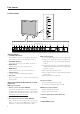
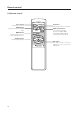
Part names
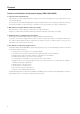
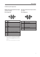
RGB-2 input terminal (mini D-sub 15-pin
connector: female)
Pin arrangement
Pin No. Signal
1R
2G
3B
4 NC (not connected)
5 GND
6 GND
7 GND
8 GND
9 NC (not connected)
10 GND
11 NC (not connected)
12 Remote control signal output (Note)
13 HD or H/V SYNC
14 VD
15 NC (not connected)
Note: This is a pin for controlling an external add-on
peripheral device to be released in the near future.
1 This can be turned ON/OFF with the remote out
switch 7.
When ''OFF'' is selected, it is NC (not connected).
RS-232C terminal (D-sub 9-pin connec-
tor: male)
Pin arrangement
Pin No. Signal
1 NC (not connected)
2 TxD (Transmit Data)
3 RxD (Receive Data)
4 NC (not connected)
5 GND
6 NC (not connected)
7 NC (not connected)
8 RTS (Reguest To Send)
9 NC (not connected)
2.4 Various pin arrangements
5
1
10
15
11
6
15
6
9