
Specifications


8
STANDBY
/ON
INPUT
MENU
ADJUST
SET
VD HD B G R C Y OUT IN
75 2.2k
OFF ON
(
Ω
)
OFF ON
(H/V SYNC) RGB-1 (ON SYNC) Y/C
SYNCREMOTE G ON SYNC
VIDEO RS-232CRGB-2
1
2
3
4
5
6
8
97-0=~!@#$%^& (*
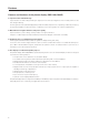
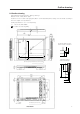
2.3 Part names
Part names
<Terminals and power supply section>
(The terminals and power supply section are located at the back of the plasma
display main body.)
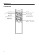
<Control Panel>
1 STANDBY/ON indicator
The indicator is red when in standby mode and turns
green when the power to the display is turned on.
2 STANDBY/ON button
Press to turn the power to the display on and off.
3 INPUT button
Press to switch the various input functions.
4 MENU button
Press to enter the menu screen and exit from it.
5 ADJUST button
Use the +/– buttons to adjust picture quality.
6 SET button
Press to finalize menu selections when adjusting
picture quality.
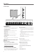
<Rear Panel Terminals/Connections to Pow-
er Source>
RGB-2 input terminals
7 Remote control out switch (ON/OFF)
This switch will output remote control commands from
the RGB-2 (D-SUB 15-pin) terminal to control external
peripheral devices planned for future sales release.
Normally be sure to use set to OFF.
8 MINI D-SUB 15-pin terminal
9 G on Sync mode selection switch (ON/OFF)
If the images become greenish when an external
device is connected to the RGB-2 input terminal, turn
ON the G on SYNC mode. Normally set to OFF.
RGB-1 input terminals
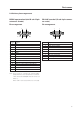
0 Sync Signal Input Impedance switch (75 Ω/2,2 kΩ)
- Vertical Sync Signal Input terminal: (75 Ω/2,2 kΩ,
switchable with the Sync Signal Input Impedance
switch)
= Horizontal or Composite Sync Signal Input terminal:
(75 Ω/2,2 kΩ, switchable with the Sync Signal Input
Impedance switch)
~ Blue Signal Input terminal: 75 Ω
! Green or Green with Sync Signal Input terminal (ON
SYNC) :75 Ω
@ Red Signal Input terminal: 75 Ω
Y/C input terminals
# Color Signal Input terminal: 75 Ω
$ Luminance Signal Input terminal: 75 Ω
VIDEO input/output terminals
% Video Output terminal: 75 Ω
^ Video Input terminal: 75 Ω
& Control Signal Input terminal (RS-232C)
* AC inlet
( MAIN POWER switch