
Instruction manual


Attaching Extended Fence Gage:
1. Place Extended Fence Gage (5/8 x 3-1/2” material) on table. Bolt to fence bracket with screws provided.
Adjust fence gage so measurement rule is correctly set:
A. With a scale or ruler touching the side of the tips of the blade, measure a distance away from blade.
Be sure the ruler and the tape on the fence gage read the same. This may be visually deceiving.
Use a 90° square to check.
B. Adjust fence, left to right, as necessary.
C. Both fences, left and right, must be in perfect alignment. Use a long straight edge for this purpose.
(see Diagrams “B” below and Diagram “E” on Page No. 7).
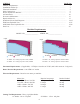
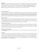
Diagram “B”
Blade Installation:
Before setting blades on spindle, always shut off or disconnect air supply. With motor OFF and power disconnected,
loosen wing nut on Bottom Blade Guard Strap, P/N 6F07B (see Diagram “D“ below) and swing down. Now, lift
main blade guard, exposing Spindle Assembly.
1. Remove Spindle Nut, P/N 4B1P48 and Outer Flange, P/N 4BM43. If necessary, hold blade in hand with rag
or lower blade into a piece of wood. Push down with a wrench.
2. Place blade on spindle with tips pointing down. Make sure Slinger (inner flange), P/N 4BM44, and blade
surface are clean before putting blade on spindle. This is a critical surface and is ground within .0005
flatness. Any debris or dust will wear this surface. Wipe both surfaces (blade and slinger) with a clean rag.
A. The blade must ALWAYS rotate to the rear of the machine on the underside of the blade
(see Diagram “D“). Always check rotation before cutting a piece of material.
3. Replace Outer Flange, P/N 4BM43 and Spindle Nut, P/N 4B1P48 as before and tighten (refer to
Diagram “C”). Pull up with wrench. Do not over-tighten. Snugging the blade is all that is necessary.
If blades were purchased from CTD, your machine has been set with your blades. If not, blade diameters may
vary. Check to see if the blade contacts the base or disc in the down position. If repositioning is necessary, adjust
down stop bolt located under Arm Casting, P/N 4BC01 (refer to Page No. 11).
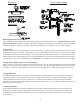
Diagram “C” Diagram “D”
arm
casting
slinger
blade
flange
spindle
spindle
nut
-4-