
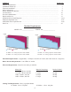
Instruction manual


These machines are general purpose in their design, therefore the user should attach any addi-
tional guarding to the blade guard or table base if the cutting application causes
unsafe blade exposure.
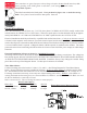
This label is attached to the blade guard. Never put hand or fingers near or under the moving
blade. Use a piece of wood to remove short pieces from saw.
Electrical Installation:
The CTD A500 Series Cut-Off Saws use 7-1/2 H.P. three phase 1725 RPM, 60 HZ TEFC (totally enclosed fan
cooled) motors on a NEMA 213T or 215T Frame. CTD uses a speed up drive so that the blade will run at approxi-
mately 2900 RPM for a 16” blade and 2700 RPM for a 20” blade. Optional motors are 10 H.P. & 15 H.P.
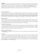
Electrical installation should be performed by a qualified and certified electrician. A lock-out or disconnect switch
is located on the magnetic starter between your main electrical panel and the machine. This disconnect switch is
used to shut off power to the machine and should be used whenever the blades are changed or at any time the machine
is serviced and the blade is exposed. A Magnetic Starter (OSHA required) is standard on the machine. The starter
protects the motor from overheating and will not allow the motor to restart itself after power outages or undervoltage
situations.
Electrical Installation of Power to Starter by a Qualified Electrician:
All wiring from the motor to the starter has been completed and tested at the factory several times. The voltage has
been clearly tagged. DO NOT CONNECT ANY VOLTAGE THAT IS DIFFERENT THAN THE TAGGED VOLTAGE,
AS THIS MAY CAUSE SEVERE DAMAGE AND DANGER. Consult the factory if any changes are needed. Bring
power lines to the top of the Magnetic Starter. Use dust proof connectors if available.
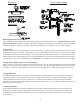
Three Phase Motors:
Connect incoming power line leads to L1 (line 1), L2, and L3. (See Wiring Diagram for Three Phase Motors
below.) Green ground wire must be grounded to enclosure. Be sure to check rotation as polarities may be differ-
ent. The blade must rotate down and to the rear on the underside of the blade (see Diagram “D” on Page No. 4).
If a change in rotation is necessary, reverse any two of the incoming power wires. Example: If the blades are
running backwards and incoming wires are connected White L1, Black L2, and Red L3, switch the Black wire with
the Red so that Black is connected to L3 and
Red is connected to L2. This will change the motor to rotate properly.
Wiring Diagram for Magnetic Starter
Motor Load Amperes
Motor Size 208 Volt 230 Volt 460 Volt
7-1/2 H.P., 3 Phase 21.5 amps 20 amps 10 amps
10 H.P., 3 Phase 28 amps 26 amps 13 amps
-5-