
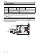
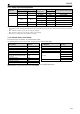
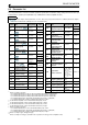
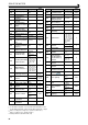
Specifications

30
PRECAUTIONS FOR USE OF THE INVERTER
Vector control is available with an encoder-equipped motor. And such an encoder must be directly connected to a motor
shaft without any backlash. (Real sensorless vector control, PM sensorless control do not require an encoder.)
Inverter input side magnetic contactor (MC)
On the inverter input side, connect an MC for the following purposes. (Refer to the Instruction Manual.)
– To release the inverter from the power supply when a fault occurs or when the drive is not functioning (e.g. emergency
stop operation). For example (does not apply for FR-A842), MC avoids overheat or burnout of the brake resistor when
heat capacity of the resistor is insufficient or brake regenerative transistor is damaged with short while connecting an
optional brake resistor.
– To prevent any accident due to an automatic restart at restoration of power after an inverter stop made by a power
failure
– To separate the inverter from the power supply to ensure safe maintenance and inspection work.
If using an MC for emergency stop during operation, select an MC regarding the inverter input side current as JEM1038-
AC-3 class rated current.
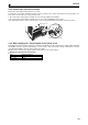
Handling of inverter output side magnetic contactor
Switch the magnetic contactor between the inverter and motor only when both the inverter and motor are at a stop.
When the magnetic contactor is turned ON while the inverter is operating, overcurrent protection of the inverter and
such will activate. When MC is provided for switching to the commercial power supply, for example, switch it ON/OFF
after the inverter and motor have stopped.
A PM motor is a synchronous motor with high-performance magnets embedded inside. High-voltage is generated at the
motor terminals while the motor is running even after the inverter power is turned OFF. Before wiring or inspection,
confirm that the motor is stopped. In an application, such as fan and blower, where the motor is driven by the load, a
low-voltage manual contactor must be connected at the inverter's output side, and wiring and inspection must be
performed while the contactor is open. Otherwise you may get an electric shock.
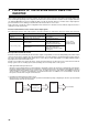
Countermeasures against inverter-generated EMI
When the motor speed is unstable, due to change in the frequency setting signal caused by electromagnetic noises
from the inverter, take the following measures when applying the motor speed by the analog signal:
– Do not run the signal cables and power cables (inverter I/O cables) in parallel with each other and do not bundle them.
– Run signal cables as far away as possible from power cables (inverter I/O cables).
– Use shielded cables as signal cables.
– Install a ferrite core on the signal cable (Example: ZCAT3035-1330 TDK).
Instructions for overload operation
When performing operation of frequent start/stop of the inverter, increase/decrease in the temperature of the transistor
element of the inverter may repeat due to a continuous flow of large current, shortening the life from thermal fatigue.
Since thermal fatigue is related to the amount of current, the life can be increased by reducing bound current, starting
current, etc. Decreasing current may increase the life. However, decreasing current will result in insufficient torque and
the inverter may not start. Adding a margin to the current can eliminate such a condition. For a general-purpose motor,
use an inverter of a higher capacity (up to 2 ranks). For a PM motor, use an inverter and a PM motor of higher capacities
(up to 2 ranks).
Make sure that the specifications and rating match the system requirements.
FR-A842 models only: Connect the converter unit and the inverter correctly. For details refer to the FR-CC2 Instruction
Manual.