
Specifications
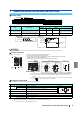

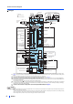


Terminal connection diagrams
WIRING
5
WIRING
3.1 Terminal connection diagrams
FM type
For the FR-A820-03800(75K) or higher and FR-A840-02160(75K) or higher, always connect an optional DC reactor (FR-HEL). (When selecting a DC reactor, refer to
page 25, and select one suitable for the applicable motor capacity.) If a jumper is installed across the terminals P1 and P/+, remove the jumper before installing the DC
reactor.
When using separate power supply for the control circuit, remove the jumper between R1/L11 and S1/L21.
The function of these terminals can be changed with the input terminal assignment (Pr.178 to Pr.189). (Refer to page 17.)
Terminal JOG is also used as the pulse train input terminal. Use Pr.291 to choose JOG or pulse.
Terminal input specifications can be changed by analog input specification switchover
(Pr.73, Pr.267)
. To input a voltage (0 to 5 V/ 0 to 10 V), set the voltage/current input switch
OFF. To input a current (4 to 20 mA), set the voltage/current input switch ON. Terminals 10 and 2 are also used as a PTC input terminal.
(Pr.561)
(Refer to the Instruction Manual
(Detailed).)
It is recommended to use 2W1k when the frequency setting signal is changed frequently.
If connecting a brake resistor, remove the jumper between PR and PX (FR-A820-00046(0.4K) to 00490(7.5K), FR-A840-00023(0.4K) to 00250(7.5K)). The terminal PR
is equipped in FR-A820-00046(0.4K) to 01250(22K), FR-A840-00023(0.4K) to 01800(55K). Install a thermal relay to prevent overheating and damage of discharging
resistors. (Refer to the Instruction Manual
(Detailed)
.)
The function of these terminals can be changed with the output terminal assignment (Pr.195, Pr.196). (Refer to page 17.)
The function of these terminals can be changed with the output terminal assignment (Pr.190 to Pr.194). (Refer to page 17.)
The terminal F/C(FM) can be used to output pulse trains as open collector output by setting Pr.291.
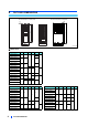
Not required when calibrating the scale with the operation panel.
ÒÑÌÛ
! To prevent a malfunction due to noise, keep the signal cables 10 cm or more away from the power cables. Also, separate the main circuit cables at the input side from
the main circuit cables at the output side.
! After wiring, wire offcuts must not be left in the inverter. Wire offcuts can cause an alarm, failure or malfunction. Always keep the inverter clean. When drilling mounting
holes in an enclosure etc., take caution not to allow chips and other foreign matter to enter the inverter.
! Set the voltage/current input switch correctly. Incorrect setting may cause a fault, failure or malfunction.
Ðï
Î
ÐíÐÎÒñóÐñõ
ÚÎóßèîðóððééðøïëÕ÷ ¬± ðïîëðøîîÕ÷ô
ÚÎóßèìðóððìéðøïèòëÕ÷ ¬± ðïèððøëëÕ÷
̸®»»ó°¸¿-»
ßÝ °±©»®
-«°°´§
ÓÝÝÞ
ÎñÔï
ÍñÔî
ÌñÔí
ÎïñÔïï
ÍïñÔîï
ÐÝ
îìÊÜÝ °±©»® -«°°´§
øݱ³³±² º±® »¨¬»®²¿´ °±©»® -«°°´§ ¬®¿²-·-¬±®÷
Ú±®©¿®¼ ®±¬¿¬·±² -¬¿®¬
못®-» ®±¬¿¬·±² -¬¿®¬
ͬ¿®¬ -»´ºó¸±´¼·²¹ -»´»½¬·±²
Ó·¼¼´» -°»»¼
Ø·¹¸ -°»»¼
Ô±© -°»»¼
Ö±¹ ±°»®¿¬·±²
Í»½±²¼ º«²½¬·±² -»´»½¬·±²
Ñ«¬°«¬ -¬±°
λ-»¬
Ì»®³·²¿´ ì ·²°«¬ -»´»½¬·±²
øÝ«®®»²¬ ·²°«¬ -»´»½¬·±²÷
Í»´»½¬·±² ±º ¿«¬±³¿¬·½ ®»-¬¿®¬
¿º¬»® ·²-¬¿²¬¿²»±«-
°±©»® º¿·´«®»
Ú®»¯«»²½§ -»¬¬·²¹ -·¹²¿´- øß²¿´±¹÷
ïðÛøõïðÊ÷
ïðøõëÊ÷
î
øß²¿´±¹ ½±³³±²÷
î
í
ï
ß«¨·´·¿®§
·²°«¬
Ì»®³·²¿´ ì ·²°«¬
øÝ«®®»²¬ ·²°«¬÷
ï
ì
Ú®»¯«»²½§ -»¬¬·²¹
°±¬»²¬·±³»¬»®
Ϋ²²·²¹
Ë° ¬± º®»¯«»²½§
ײ-¬¿²¬¿²»±«-
°±©»® º¿·´«®»
Ѫ»®´±¿¼
Ú®»¯«»²½§ ¼»¬»½¬·±²
Ñ°»² ½±´´»½¬±® ±«¬°«¬ ½±³³±²
Í·²µñ-±«®½» ½±³³±²
ÚñÝ
øÚÓ÷
ÍÜ
ݱ²¬®±´ ·²°«¬ -·¹²¿´-
øÒ± ª±´¬¿¹» ·²°«¬ ¿´´±©»¼÷
Ö«³°»®
Ö«³°»®
Ó±¬±®
λ´¿§ ±«¬°«¬ ï
øÚ¿«´¬ ±«¬°«¬÷
Ýï
Þï
ßï
Ë
Ê
É
Ðï
ײ¼·½¿¬±®
øÚ®»¯«»²½§ ³»¬»®ô »¬½ò÷
õó
øó÷
øõ÷
ß²¿´±¹ -·¹²¿´ ±«¬°«¬
ø𠬱 oïðÊÜÝ÷
Û¿®¬¸
øÙ®±«²¼÷
ßÓ
ë
ÜÝ𠬱 oëÊ -»´»½¬¿¾´»
ÜÝ𠬱 oïðÊ
Ó«´¬·ó-°»»¼
-»´»½¬·±²
Ñ°»² ½±´´»½¬±® ±«¬°«¬
Ó±ª·²¹ó½±·´ ¬§°»
ï³ß º«´´ó-½¿´»
ݱ²¬¿½¬ ·²°«¬ ½±³³±²
Ý¿´·¾®¿¬·±²
®»-·-¬±®
Û¿®¬¸
øÙ®±«²¼÷
Û¿®¬¸
øÙ®±«²¼÷
Ó¿·² ½·®½«·¬ ¬»®³·²¿´
ݱ²¬®±´ ½·®½«·¬ ¬»®³·²¿´
ÜÝ𠬱 ëÊ
ÜÝ𠬱 ïðÊ
-»´»½¬¿¾´»
ÓÝ
Ó¿·² ½·®½«·¬
Ýî
Þî
ßî
λ´¿§ ±«¬°«¬ î
λ´¿§ ±«¬°«¬
Ó
ÜÝ𠬱 îð³ß
ÜÝ𠬱 ëÊ
ÜÝ𠬱 ïðÊ
-»´»½¬¿¾´»
ÜÝì ¬± îð³ß
ÌÈÜõ
Ì»®³·²¿¬·²¹
®»-·-¬±®
ÌÈÜó
ÎÈÜõ
ÎÈÜó
ÍÙ
Ü¿¬¿
¬®¿²-³·--·±²
ÙÒÜ
ÎÍóìèë ¬»®³·²¿´-
ÐË
½±²²»½¬±®
ËÍÞ ß
½±²²»½¬±®
ËÍÞ
³·²· Þ
½±²²»½¬±®
Í×ÒÕ
ÍÑËÎÝÛ
ݱ²²»½¬±® º±® °´«¹ó·² ±°¬·±² ½±²²»½¬·±²
ÍÌÚ
ÍÌÎ
ÍÌÐøÍÌÑÐ÷
ÎØ
ÎÓ
ÎÔ
ÖÑÙ
ÎÌ
ÓÎÍ
ÎÛÍ
ßË
ÝÍ
ÍÜ
ÎËÒ
ÍË
×ÐÚ
ÑÔ
ÚË
ÍÛ
Ü¿¬¿
®»½»°¬·±²
øõ÷
øó÷
ë
ÛÓÝ º·´¬»®
ÑÒñÑÚÚ
½±²²»½¬»®
ÑÒ
ÑÚÚ
õîì
îìÊ »¨¬»®²¿´ °±©»®
-«°°´§ ·²°«¬
ÍÜ
ݱ³³±² ¬»®³·²¿´
ÊÝÝ
øõ÷
øó÷
ëÊ
øл®³·--·¾´» ´±¿¼ ½«®®»²¬ ïðð³ß÷
Í·²µ ´±¹·½
Û¿®¬¸ øÙ®±«²¼÷
Î
Î
½±²²»½¬±® ï ½±²²»½¬±® î
½±²²»½¬±® í
Ö«³°»®
Ö«³°»®
ÐÈÐÎÒñóÐñõ
ݱ²¬®±´ ½·®½«·¬
ײ·¬·¿´ ª¿´«»
ײ·¬·¿´ ª¿´«»
ײ·¬·¿´ ª¿´«»
ÑÒ
ì
î
ÑÚÚ
ʱ´¬¿¹»ñ½«®®»²¬
·²°«¬ -©·¬½¸
Þ®¿µ» «²·¬
øÑ°¬·±²÷
Þ®¿µ» «²·¬
øÑ°¬·±²÷
ÜÝ ®»¿½¬±®
øÚÎóØÛÔ÷
ÜÝ ®»¿½¬±®
øÚÎóØÛÔ÷
Þ®¿µ» ®»-·-¬±®
øÚÎóßÞÎ÷
Þ®¿µ» ®»-·-¬±®
øÚÎóßÞÎ÷
Í¿º»¬§ ³±²·¬±® ±«¬°«¬
Í¿º»¬§ ³±²·¬±® ±«¬°«¬ ½±³³±²
ͱ
ÍÑÝ
Íï
Íî
ÐÝ
ÍÜ
Í×Ý
Í¿º»¬§ -¬±° -·¹²¿´
Í¿º»¬§ -¬±° ·²°«¬ øݸ¿²²»´ ï÷
͸±®¬·²¹
©·®»
Í¿º»¬§ -¬±° ·²°«¬ ½±³³±²
Í¿º»¬§ -¬±° ·²°«¬ øݸ¿²²»´ î÷
îìÊ
ײ®«-¸ ½«®®»²¬
´·³·¬ ½·®½«·¬
îìÊ
Ñ«¬°«¬ -¸«¬±ºº
½·®½«·¬