
Datasheet
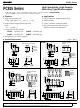

PC815 Series
*1 Pulse width<=100
µ
s, Duty ratio : 0.001
*3 For 10 seconds
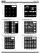
Parameter Symbol MIN. TYP. MAX. Unit
Input
V
F
- 1.2 1.4 V
V
FM
- - 3.0 V
I
R
--10µA
C
t
- 30 250 pF
Output I
CEO
--10
-6
A
Transfer
charac-
teristics
CTR 600 %
V
CE
(
sat
)
- 0.8 1.0 V
5x10
10
10
11
- Ω
0.6 1.0 pF
1 6 - kHz
-
-
60 300 µ s
- 53 250 µ s
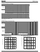
■ Absolute Maximum Ratings
(
Ta= 25˚C
)
■ Electro-optical Characteristics
(
Ta= 25˚C
)
Parameter Symbol Rating Unit
Input
Forward current I
F
50 mA
*1
Peak forward current I
FM
1A
Reverse voltage V
R
6V
Power dissipation P 70 mW
Output
Collector-emitter voltage V
CEO
35 V
Emitter-collector voltage V
ECO
6V
Collector current I
C
80 mA
Collector power dissipation P
C
150 mW
Total power dissipation P
tot
200 mW
*2
Isolation voltage V
iso
Operating temperature T
opr
- 30 to + 100 ˚C
Storage temperature T
stg
- 55 to + 125 ˚C
*3
Soldering temperature T
sol
260 ˚C
Forward voltage
Peak forward voltage
Reverse current
Terminal capacitance
Collector dark current
Current transfer ratio
Collector-emitter saturation voltage
Conditions
I
F
= 20mA
I
FM
= 0.5A
V
R
=4V
V= 0, f= 1kHz
V
CE
= 10V, I
F
=0
I
F
= 1mA, V
CE
=2V
I
F
= 20mA, I
C
= 5mA
V= 0, f= 1MHz
V
CE
= 2V, I
C
= 2mA, R
L
= 100Ω
V
CE
= 2V, I
C
= 10mA, R
L
= 100Ω
Isolation resistance R
ISO
Floating capacitance C
f
Cut-off frequency f
c
Response time
Rise time t
r
Fall time t
f
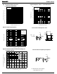
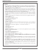
0
-30
10
F
(
mA
)
0 25 50 75 100 125
20
30
40
50
60
Fig. 1 Forward Current vs.
Ambient Temperature
(
˚C
)
0
0 125
100
200
50
150
25 50 75 100
Ambient Temperature
C
(
mW
)
-30
(
˚C
)
Fig. 2 Collector Power Dissipation vs.
Collector power dissipation P
Forward current I
5 000
*2 40 to 60% RH, AC for 1 minute
DC500V, 40 to 60% RH
Ambient temperature Ta Ambient temperature Ta
V
rms
- 7 500