PG-D3750W Quick Start MODEL Introduction DATA PROJECTOR Setup OPERATION MANUAL Connections Basic Operation Useful Features Appendix
IMPORTANT • For your assistance in reporting the loss or theft of your Projector, please record the Model and Serial Number located on the bottom of the projector and retain this information. • Before recycling the packaging, please ensure that you have checked the contents of the carton thoroughly against the list of “Supplied accessories” on page 11. ii Model No.: Serial No.
SPECIAL NOTE FOR USERS IN THE U.K. The mains lead of this product is fitted with a non-rewireable (moulded) plug incorporating a 10A fuse. Should the fuse need to be replaced, a BSI or ASTA approved BS 1362 fuse marked or and of the same rating as above, which is also indicated on the pin face of the plug, must be used. Always refit the fuse cover after replacing the fuse. Never use the plug without the fuse cover fitted.
The supplied CD-ROM contains operation instructions in English, German, French, Spanish, Italian, Dutch, Swedish, Portuguese, Chinese and Korean. Carefully read through the operation instructions before operating the projector. Die mitgelieferte CD-ROM enthält Bedienungsanleitungen in Englisch, Deutsch, Französisch, Spanisch, Italienisch, Niederländisch, Schwedisch, Portugiesisch, Chinesisch und Koreanisch. Bitte lesen Sie die Bedienungsanleitung vor der Verwendung des Projektors sorgfältig durch.
Introduction Introduction Before using the projector, please read this operation manual carefully. ENGLISH There are two important reasons for prompt warranty registration of your new SHARP Projector, using the REGISTRATION CARD packed with the projector. 1. WARRANTY This is to assure that you immediately receive the full benefit of the parts, service and labor warranty applicable to your purchase. 2.
INFORMATION This equipment has been tested and found to comply with the limits for a Class A digital device, pursuant to Part 15 of the FCC Rules. These limits are designed to provide reasonable protection against harmful interference when the equipment is operated in a commercial environment. This equipment generates, uses, and can radiate radio frequency energy and, if not installed and used in accordance with the operation manual, may cause harmful interference to radio communications.
Introduction How to Read this Operation Manual ■ The specifications are slightly different, depending on the model. However, you can connect and operate all models in the same manner. • In this operation manual, the illustration and the screen display are simplified for explanation, and may differ slightly from the actual display.
Contents Preparing Introduction Useful Features How to Read this Operation Manual ......3 Contents .................................................4 IMPORTANT SAFEGUARDS ..................6 How to Access the PDF Operation Manuals..............................................10 Accessories ..........................................11 Part Names and Functions ...................12 Operating with the Remote Control......32 Projector................................................. 12 Rear View ...........
Introduction Setting up the Projector Network Environment (“Network” Menu)..........49 Setting a Password ................................ 49 DHCP Client Setting ............................... 50 TCP/IP Setting........................................ 50 Confirming the Projector Information....... 50 Troubleshooting with the “Help” Menu.......................................51 Utilizing the “Help” Menu Functions ........ 51 Reference Appendix Maintenance .........................................
IMPORTANT SAFEGUARDS CAUTION: Please read all of these instructions before you operate this product and save these instructions for later use. Electrical energy can perform many useful functions. This product has been engineered and manufactured to assure your personal safety. BUT IMPROPER USE CAN RESULT IN POTENTIAL ELECTRICAL SHOCK OR FIRE HAZARDS. In order not to defeat the safeguards incorporated in this product, observe the following basic rules for its installation, use and servicing. 1.
Do not overload wall outlets, extension cords, or integral convenience receptacles as this can result in a risk of fire or electric shock. 16. Object and Liquid Entry Never push objects of any kind into this product through openings as they may touch dangerous voltage points or short-out parts that could result in a fire or electric shock. Never spill liquid of any kind on the product. 17.
Observe the following safeguards when setting up your projector. Caution concerning the lamp unit ■ Potential hazard of glass particles if lamp ruptures. In case of lamp rupture, contact your nearest Sharp Authorized Projector Dealer or Service Center for replacement. See “Regarding the Lamp” on page 55.
Using the projector in other countries ■ If you are not to use the projector for a long time or before moving the projector, make certain you unplug the power cord from the wall outlet, and disconnect any other cables connected to it. ■ Do not carry the projector by holding the lens. ■ When storing the projector, ensure that you close the lens shutter. ■ Do not expose the projector to direct sunlight or place next to heat sources.
How to Access the PDF Operation Manuals PDF operation manuals in several languages are included in the CD-ROM. To utilize these manuals, you need to install Adobe® Reader ® on your computer (Windows® or Macintosh®). Please download Adobe® Reader ® from the Internet (http://www.adobe.com). Accessing the PDF Manuals For Windows®: Insert the CD-ROM in the CD-ROM drive. Double click the “My Computer” icon. Double click the “CD-ROM” drive.
Introduction Accessories Supplied accessories Two R-6 batteries (“AA” size, UM/SUM-3, HP-7 or similar) Remote control Power cord* (1) For U.S. and Canada, etc. (6' (1.8 m)) (2) For Europe, except U.K. (6' (1.8 m)) RGB cable (10' (3.0 m)) (3) (4) For U.K. and Singapore (6' (1.8 m)) For Australia, New Zealand and Oceania (6' (1.
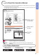
Part Names and Functions Numbers in Z refer to the main pages in this operation manual where the topic is explained. Projector Top View AUTO SYNC button For automatically adjusting images when connected to a computer. 33 STANDBY/ON button For turning the power on and putting the projector into standby mode. 26 Power indicator 26, 53 Lamp indicator 26, 53 Temperature warning indicator KEYSTONE button For entering the Keystone Correction mode.
Introduction Numbers in Z refer to the main pages in this operation manual where the topic is explained. 22 VIDEO input terminal Rear View Terminal for connecting video equipment. Terminals 22 S-VIDEO input terminal MONITOR OUT terminal 23 (Output terminal for computer RGB and component signals. Shared for COMPUTER/ COMPONENT1 and 2) Terminal for connecting a monitor. COMPUTER/COMPONENT1 and 2 input terminals Terminals for computer RGB and component signals.
Part Names and Functions (Continued) STANDBY button 26 For putting the projector into the standby mode. 26 ON button COMPUTER1/2, HDMI, 29 S-VIDEO, VIDEO buttons For switching to the respective input modes. 33 FREEZE button BREAK TIMER button 32 For displaying the break time. MAGNIFY buttons 33 For enlarging/reducing part of the image.
1 Pull down the tab on the cover and remove the cover towards the direction of the arrow. 2 Insert the batteries. 3 Insert the lower tab of the cover into the opening, and lower the cover until it clicks in place. Introduction Inserting the Batteries • Insert the batteries making sure the polarities correctly match the m and n marks inside the battery compartment. Incorrect use of the batteries may cause them to leak or explode.
Quick Start This section shows the basic operation (projector connecting with the computer). For details, see the page described below for each step. Setup and Projection In this section, connection of the projector and the computer is explained using one example. 3 STANDBY/ON button 8 5 KEYSTONE button 8 STANDBY button 3 ON button 5 Adjustment buttons 6 COMPUTER1 button (P/R/O/Q) 6 INPUT buttons 4 Zoom ring 4 Focus ring 5 Adjustment buttons (P/R/O/Q) 4 HEIGHT 5 ADJUST lever 1.
4. Adjust the projected image 1 2 3 Adjusting the focus. Adjusting the height. Adjusting the picture size. BP. 27 Quick Start 5. Correct trapezoidal distortion Correcting trapezoidal distortion using Keystone Correction. On the projector Shrinks upper side. Shrinks lower side. On the remote control BP. 28 6. Select the INPUT mode Select the “COMPUTER1” using INPUT on the projector or COMPUTER1 on the remote control.
Setting up the Projector Setting up the Projector For optimal image quality, position the projector perpendicular to the screen with the projector's feet flat and level. Doing so will eliminate the need for Keystone correction and provide the best image quality. (See page 28.) Standard Setup (Front Projection) ■ Place the projector at the required distance from the screen according to the desired picture size. (See page 20.
Projection (PRJ) Mode The projector can use any of the 4 projection modes shown in the diagram below. Select the mode most appropriate for the projection setting in use. (You can set the PRJ mode in “SCRADJ” menu. See page 44.
Setting up the Projector (Continued) Screen Size and Projection Distance 16:10 Signal Input (Normal Mode) Picture (Screen) size Diag.
Connecting the Projector to Other Equipment Before connecting, ensure that the power cord of the projector is unplugged from the AC outlet and turn off the equipment to be connected. After making all connections, turn on the projector and then the other pieces of equipment. When connecting a computer, ensure that it is the last equipment to be turned on after all the connections are made.
Connecting the Projector to Other Equipment (Continued) Equipment Video equipment Terminal on connected equipment HDMI output terminal HDMI cable (commercially available) Terminal on the projector HDMI Component video output terminal 3 RCA to mini D-sub 15 pin cable (optional, AN-C3CP2) COMPUTER/ COMPONENT1 or 2 S-video cable (commercially available) S-VIDEO Video cable (commercially available) VIDEO S-video output terminal Video output terminal Camera/Video game Component video output terminal
Equipment Audio equipment Terminal on connected equipment Cable ø3.5 mm audio output terminal ø3.
Controlling the Projector by a Computer When the RS-232C terminal on the projector is connected to a computer with an RS-232C serial control cable (cross type, commercially available), the computer can be used to control the projector and check the status of the projector. Refer to the “SETUP MANUAL” contained on the supplied CD-ROM for “RS-232C Specifications and Commands”.
When connecting to the LAN terminal using a LAN cable TX/RX LED (yellow) Illuminates when transmitting/receiving data. LINK LED (green) Illuminates when linked. * To ensure safety, do not connect the LAN terminal with any cables that may cause excessive voltage such as a telephone line. Hub or Computer To LAN terminal Connections LAN cable (Category 5 type, commercially available) Note • When connecting to a hub, use a straight-through Category 5 (CAT.5) type cable (commercially available).
Turning the Projector On/Off Info Turning the Projector On Note that the connections to external equipment and power outlet should be done before performing the operations written below. (See pages 21 to 25.) Open the lens shutter fully and press STANDBY/ON on the projector or ON on the remote control.
Image Projection Adjusting the Projected Image Zoom ring Focus ring 1 Adjusting the Focus You can adjust the focus with the focus ring on the projector. Rotate the focus ring to adjust the focus while watching the projected image. 2 Adjusting the Height The height of the projector can be adjusted using the adjustment feet. When the screen is above the projector, the projection image can be made higher by adjusting the projector.
Image Projection (Continued) Correcting Trapezoidal Distortion Adjustment buttons (P/R/O/Q) When the image is projected either from the top or from the bottom towards the screen at an angle, the image becomes distorted trapezoidally. The function for correcting trapezoidal distortion is called Keystone Correction.
Switching the Input Mode COMPUTER1/2, HDMI, S-VIDEO, VIDEO buttons Select the appropriate input mode for the connected equipment. Press COMPUTER1/2, HDMI, S-VIDEO or VIDEO on the remote control to select the input mode. AV MUTE button VOL +/– (Volume) buttons • When you press INPUT on the projector, the INPUT list appears. Press P/R to switch the INPUT mode. Adjusting the Volume Press VOL +/– on the remote control or –O/Q+ on the projector to adjust the volume.
Image Projection (Continued) Resize Mode This function allows you to modify or customize the resize mode to enhance the input image. Depending on the input signal, you can choose a desired image. Press RESIZE. RESIZE button • See page 43 for setting on menu screen.
VIDEO/DTV Input signal Video/DTV Image type Output screen image NORMAL AREA ZOOM V-STRETCH STRETCH *1 4:3 aspect ratio 480I, 480P, 576I, 576P, NTSC, PAL, SECAM *1 Squeeze *1 Letter box *1 720P, 1035I, 1080I, 1080P 16:9 aspect ratio *1 16:9 aspect ratio *1 —*2 16:9 aspect ratio 540P *1 16:9 aspect ratio (4:3 aspect ratio in 16:9) About Copyrights • When using the RESIZE function to select an image size with a different aspect ratio to a TV program or video image, the image will look different fr
Operating with the Remote Control BREAK TIMER button FREEZE button MAGNIFY buttons Displaying the Pointer 1 POINTER button Press POINTER and press P/R/ O/Q on the remote control to move the pointer. • Press EFFECT to change the pointer icon (5 types). SPOT button Star Adjustment buttons (P/R/O/Q) EFFECT button PICTURE MODE button ECO+QUIET button 2 Finger1 Finger2 Heart Underline Press POINTER again. • The pointer will disappear.
Auto Sync (Auto Sync Adjustment) Displaying an Enlarged Portion of an Image Auto Sync function works when detecting input signal after the projector turns on. Graphs, tables and other portions of projected images can be enlarged. This is helpful when providing more detailed explanations. Press AUTO SYNC to manually adjust with Auto Sync function. 1 Note Press MAGNIFY on the remote control. • Enlarges the image. • Pressing or MAGNIFY enlarges or reduces the projected image.
Operating with the Remote Control (Continued) Using the Remote Control as the Wireless Computer Mouse When connecting the projector and the computer with a USB cable, you can use the remote control as the computer mouse. If the computer is placed too far away from the projector to be connected via the USB cable, the remote receiver (optional, AN-MR2) makes it possible to operate the projector with the remote control. For details, see the operation manual of the receiver.
Menu Items The following shows the items that can be set in the projector. “Picture” menu Main menu Picture PAGE 1 Picture Page 40 SCR Picture Mode Contrast Bright Color Tint Sharp Red Blue PRJ Net. Sub menu Standard Presentation Movie Game sRGB*1 Picture Mode Page 40 Help Standard 0 0 0 0 0 0 0 SEL./ADJ.
Menu Items (Continued) “Screen adjustment (SCR-ADJ)” menu Pict. SCR-ADJ PRJ Resize Image Shift Keystone Net. Help Main menu SCR - ADJ Stretch Page 43 0 0 Page 43 Image Shift -40 +40 Page 43 On On Off Logo Front English Overscan OSD Display Closed Caption Background PRJ Mode Language Sub menu Resize Keystone -80 Normal Full Dot By Dot Area Zoom V-Stretch Stretch +80 Page 43 Overscan [On/Off] Page 43 OSD Display [On/Off] SEL./ADJ.
“Network” menu Main menu Password [Enable/Disable] Network Pict. SCR PRJ Network Password Disable DHCP Client Off Help Page 49 Page 49 DHCP Client [On/Off] Page 50 TCP/IP Page 50 TCP/IP MAC Address X X : X X : X X : X X : X X : X X Projector XX-XXXX MAC Address Page 50 Projector Page 50 SEL./ADJ. ENTER END “Help” menu Pict. SCR PRJ Net.
Using the Menu Screen MENU/HELP button Adjustment buttons (P/R/O/Q) ENTER button RETURN button ENTER button Adjustment buttons (P/R/O/Q) RETURN button • Press RETURN to return to the previous screen when the menu is displayed. MENU/HELP button Menu Selections (Adjustments) Example: Adjusting “Bright”. • This operation can also be performed by using the buttons on the projector. 1 2 Press MENU/HELP. • The “Picture” menu screen for the selected input mode is displayed.
3 Press P or R and select “Bright” to adjust. • The selected item is highlighted. Picture SCR PRJ Picture Mode Contrast Bright Red Blue CLR Temp BrilliantColor TM C.M.S. Setting C.M.S. DNR Eco+Quiet Reset SEL./ADJ. Net. Help Standard 0 0 0 0 0 1 On Off On Single ADJ END Items to be adjusted Pict. To adjust the projected image while watching it SCR-ADJ Resize Image Shift Keystone PRJ Net. Help Stretch 0 0 Press ENTER. • The selected item (e.g.
Picture Adjustment (“Picture” Menu) Menu operation n Page 38 Q PAGE1 Q PAGE2 Picture 1 2 SCR Picture Mode Contrast Bright Color Tint Sharp Red Blue SEL./ADJ. PRJ Net. Help Picture Standard 0 0 0 0 0 0 0 ENTER SCR PRJ Picture Mode 3 2 4 5 6 7 END Net. Help Standard 0 1 CLR Temp BrilliantColor TM C.M.S. Setting C.M.S. Progressive DNR Eco+Quiet Reset SEL./ADJ.
Menu operation n Page 38 2 Adjusting the Image Adjustment items Contrast Bright Color*1 Tint*1 Sharp*1 Red*2 Blue*2 BrilliantColor™*2 *3 O button Q button For less contrast. For less brightness. For less color intensity. For making skin tones purplish. For less sharpness. For weaker red. For more contrast. For more brightness. For more color intensity. For making skin tones greenish. For more sharpness. For stronger red. For stronger blue. For making the effect stronger. For weaker blue.
Picture Adjustment (“Picture” Menu) (Continued) Menu operation n Page 38 5 Progressive Selectable items Description 2D Progressive Useful to display fast-moving images such as sports. 3D Progressive Useful to display relatively slowmoving images such as drama and documentary more clearly. Film Mode Reproduces the image of film source* clearly.
Adjusting the Projected Image (“SCR - ADJ” Menu) Menu operation n Page 38 Pict. SCR-ADJ 1 2 3 Resize Image Shift Keystone 4 5 6 7 8 9 Overscan OSD Display Closed Caption Background PRJ Mode Language SEL./ADJ. PRJ Net. Help Stretch 0 0 When the image is projected either from the top or from the bottom towards the screen at an angle, the image becomes distorted trapezoidally. The function for correcting trapezoidal distortion is called Keystone Correction.
Adjusting the Projected Image (“SCR - ADJ” Menu) (Continued) Menu operation n Page 38 5 Setting the On-screen Display Selectable items Description On All on-screen displays are displayed. Off INPUT/VOLUME/AV MUTE/FREEZE/ AUTO SYNC/RESIZE/PICTURE MODE/ECO+QUIET/MAGNIFY/ “An invalid button has been pressed.” are not displayed. 6 Closed Caption • Closed Caption may malfunction (white blocks, strange characters, etc.
Adjusting the Projector Function (“PRJ - ADJ” Menu) Menu operation n Page 38 Pict. 1 2 3 4 5 6 7 8 9 0 SCR PRJ-ADJ Net. Help Auto Sync Auto Power Off Auto Restart STANDBY Mode System Sound Audio Out On On On Standard On VAO Speaker Audio Input RS-232C Fan Mode System Lock Lamp Timer(Life) On Audio 1 9600bps Normal Disable 0 min 100% SEL./ADJ.
Adjusting the Projector Function (“PRJ - ADJ” Menu) (Continued) Menu operation n Page 38 6 Audio Output Type Setting This function determines whether the audio level output from the AUDIO output (MONITOR output) terminal is fixed or variable by linking with VOLUME. Selectable items Description FAO Audio output that does not vary in (Fixed Audio strength with the volume level of the Output) source projector.
Menu operation n Page 38 3 Press the 4 buttons on the remote control or on the projector to enter the preset keycode in “Old Code”. • When setting the keycode for the first time, press R on the projector for four times. PRJ - ADJ To cancel the keycode that you have already set • Press R on the projector for four times in steps 4 and 5 above.
Adjusting the Projector Function (“PRJ - ADJ” Menu) (Continued) Keylock Function Locking the Operation Buttons on the Projector Use this function to lock the operation buttons on the projector. ■ Locking the Operation Buttons Hold down ENTER on the projector for about 5 seconds while the projector is being turned on. On-screen display • The keylock function does not affect the operation with the remote control buttons. • You cannot use the keylock function while the projector is warming up.
Setting up the Projector Network Environment (“Network” Menu) Menu operation n Page 38 Pict. SCR PRJ Network 1 Password Disable 2 DHCP Client Off 3 TCP/IP Help MAC Address X X : X X : X X : X X : X X : X X 4 Projector XX-XXXX SEL./ADJ. 1 Setting a Password ENTER 2 Enter the password in “Old Password” using P, R, Q and O, then press ENTER. 3 Enter the password in “New Password” using P, R, Q and O, then press ENTER.
Setting up the Projector Network Environment (“Network” Menu) (Continued) Menu operation n Page 38 2 DHCP Client Setting Connect the LAN cable before turning the projector on. If not, the DHCP Client function does not work. Selectable items Description On Obtains configuration parameters for TCP/IP network automatically. Off Sets the TCP/IP manually. Select “On” for “DHCP Client”. “Obtaining IP Address...” appears, then the menu screen appears.
Troubleshooting with the “Help” Menu This function advises you to solve the problems during usage. Utilizing the “Help” Menu Functions ENTER button Example: When image flickering appears Operation to solve image flickering when projecting the computer RGB signal. 1 Press MENU/HELP. 2 Press O or Q to select “Help”, then press ENTER. 3 Press P or R to select “Vertical stripes or flickering image appears” on Help menu, then press ENTER. Pict. SCR PRJ MENU/HELP button Net.
Maintenance Cleaning the projector ■ Ensure that you have unplugged the power cord before cleaning the projector. ■ The cabinet as well as the operation panel is made of plastic. Avoid using benzene or thinner, as these can damage the finish on the cabinet. ■ Do not use volatile agents such as insecticides on the projector. Do not attach rubber or plastic items to the projector for long periods. The effects of some of the agents in the plastic may cause damage to the quality or finish of the projector.
Maintenance Indicators ■ The warning lights (power indicator, lamp indicator and temperature warning indicator) on the projector indicate problems inside the projector. ■ If a problem occurs, either the temperature warning indicator or the lamp indicator will illuminate red, and the projector will enter standby mode. After the projector has entered standby mode, follow the procedures given below.
Maintenance Indicators (Continued) Maintenance indicator Normal Temperature warning indicator Lamp indicator Power indicator Off Green on (Green blinks when the lamp is warming up.) Green on/ Red on Green blinks (Cooling) Abnormal Problem Cause Possible Solution • Temperatures around the projector are high. • Blocked air intake • Use the projector in an area with a temperature of lower than 95°F (+35ºC). • Relocate the projector to an area with proper ventilation. (See page 8.
Regarding the Lamp Lamp ■ It is recommended that the lamp (sold separately) be replaced when the remaining lamp life becomes 5% or less, or when you notice a significant deterioration in the picture and color quality. The lamp life (percentage) can be checked with the on-screen display. (See page 47.) ■ Purchase a replacement lamp of type AN-D400LP from your place of purchase, nearest Sharp Authorized Projector Dealer or Service Center. IMPORTANT NOTE TO U.S.
Regarding the Lamp (Continued) Removing and Installing the Lamp Unit Warning! • Do not remove the lamp unit from the projector right after use. The lamp and parts around the lamp will be very hot and may cause burns or injury. Lamp unit AN-D400LP Optional accessory Info • Do not touch the glass surface of the lamp unit or the inside of the projector. • To avoid injury to yourself and damage to the lamp, make sure you carefully follow the steps below.
4 Remove the lamp unit. 5 Insert the new lamp unit. 6 Replace the lamp unit cover. Securing screws • Loosen the securing screws from the lamp unit. Hold the lamp unit and pull it in the direction of the arrow. At this time, keep the lamp unit horizontal and do not tilt it. • Press the lamp unit firmly into the lamp unit compartment. Fasten the securing screws. • Align the tab on the lamp unit cover (1) and place it while pressing the cover (2) to close it.
Computer Compatibility Chart Computer • Multiple signal support Horizontal Frequency: 15-110 kHz, Vertical Frequency: 45-85 Hz, PC/MAC Mode Resolution Pixel Clock: 12-170 MHz Sync signal: Compatible with TTL level • Compatible with sync on green signal Horizontal frequency [kHz] Vertical frequency[Hz] Analog Support 60 70 85 60 70 85 50 60 70 72 75 85 50 56 60 70 72 75 85 50 60 70 75 85 60 60 60 75 60 60 60 60 70 75 60 75 60 75 60 60 60 60 67 75 75 ✔ ✔ ✔ ✔ ✔ ✔ ✔ ✔ ✔ ✔ ✔ ✔ ✔ ✔ ✔ ✔ ✔ ✔ ✔ ✔ ✔ ✔ ✔ ✔ ✔ ✔
Troubleshooting Problem • • • • • • No picture and no sound or • projector does not start. • • • • Check Projector power cord is not plugged into the wall outlet. Power to the external connected devices is off. The lens shutter is closed. The selected input mode is wrong. Cables are incorrectly connected to the projector. Remote control battery has run out. External output has not been set when connecting notebook computer. The lamp unit cover is not installed correctly.
Troubleshooting (Continued) Problem Maintenance indicator on • the projector illuminates or blinks in red. • The projector cannot be turned on or put into • the standby mode using STANDBY/ON on the projector. • Picture is green on • COMPUTER (Component)/ HDMI (Component). Check See “Maintenance Indicators”. Page 53 The keylock is set. If the keylock is set to “ON”, all the buttons are locked. 48 Change the input signal type setting.
For SHARP Assistance If you encounter any problems during setup or operation of this projector, first refer to the “Troubleshooting” section on pages 59 and 60. If this operation manual does not answer your question, please contact the SHARP Service departments listed below. U.S.A. Sharp Electronics Corporation 1-888-GO-SHARP (1-888-467-4277) lcdsupport@sharpsec.com http://www.sharpusa.com Canada Sharp Electronics of Canada Ltd. (905) 568-7140 http://www.sharp.
Specifications Model Display devices Resolution Lens Input terminals Output terminals Control and communication terminals F number Zoom Focus HDMI Computer/Component1/2 (mini D-sub 15 pin) S-Video (mini DIN 4 pin) Video (RCA) Audio (ø3.5 mm stereo minijack) Audio (RCA) Computer/Component (mini D-sub 15 pin) Audio (ø3.
Dimensions 4 17/32 (115) 3 15/16 (100) 1 43/64 (42.2) 13 13/64 (335) 1/ 4 (6) Units: inches (mm) 4 17/32 (115) 15 3/4 (400) M4 M4 M4 2 61/64 (75) Appendix 1 13/16 (45.75) 15/64 (5.75) 7 5/64 (179.75) 6 49/64 (171.5) M4 3 33/64 (89) 1 1/ 2 (38) 1/8 (3) 3 23/64 (85) 4 5/8 (116.
Index Accessories ······························································· 11 AC socket ·································································· 25 Adjustment buttons ··················································· 38 Adjustment foot ························································· 27 AREA ZOOM ····························································· 31 Aspect ratio ······························································· 30 Audio Input ·····························