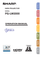
PG-LW2000 Easy Start MODEL Introduction DATA PROJECTOR Setup OPERATION MANUAL Connections Basic Operation Useful Features Appendix
IMPORTANT • For your assistance in reporting the loss or theft of your Projector, please record the Model and Serial Number located on the bottom of the projector and retain this information. • Before recycling the packag ing, please ensure that you have checked the contents of the carton thoroughly against the list of “Supplied accessories” on page 3. Model No.: Serial No.: SPECIAL NOTE FOR USERS IN THE U.K.
Introduction Introduction Before using the projector, please read this operation manual carefully. ENGLISH There are two important reasons for prompt warranty registration of your new SHARP Projector, using the REGISTRATION CARD packed with the projector. 1. WARRANTY This is to assure that you immediately receive the full benefit of the parts, service and labor warranty applicable to your purchase. 2.
INFORMATION This equipment has been tested and found to comply with the limits for a Class A digital device, pursuant to Part 15 of the FCC Rules. These limits are designed to provide reasonable protection against harmful interference when the equipment is operated in a commercial environment. This equipment generates, uses, and can radiate radio frequency energy and, if not installed and used in accordance with the operation manual, may cause harmful interference to radio communications.
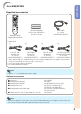
Introduction Accessories Supplied accessories Two LR03 batteries (“AAA” size, UM/SUM-4, HP-16 or similar) RGB cable (6' (1.8 m)) Remote control Power cord* (1) (2) For U.S. and For Europe, Canada, etc. except U.K. (6' (1.8 m)) (6' (1.8 m)) (3) (4) For U.K. and Singapore (6' (1.8 m)) For Australia, New Zealand and Oceania (6' (1.
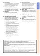
Contents Preparing Introduction Useful Features Accessories ............................................3 Contents .................................................4 IMPORTANT SAFEGUARDS ..................6 Part Names and Functions ...................10 Operating with the Remote Control......30 Top View ................................................ 10 Front View .............................................. 10 Rear View (Terminals) .............................. 11 Inserting the Batteries ..........
Introduction Keylock Function .................................... 48 Selecting the Quick Start Menu .............. 49 Setting the FUNCTION Button Operation.. 49 STANDBY Mode ..................................... 49 DLP® LinkTM ............................................ 49 DLP® LinkTM Invert .................................. 49 Returning to the Default Settings ............ 49 Checking the Lamp Life Status ............... 49 Viewing Stereoscopic 3D Images.........
IMPORTANT SAFEGUARDS CAUTION: Please read all of these instructions before you operate this product and save these instructions for later use. Electrical energy can perform many useful functions. This product has been engineered and manufactured to assure your personal safety. BUT IMPROPER USE CAN RESULT IN POTENTIAL ELECTRICAL SHOCK OR FIRE HAZARDS. In order not to defeat the safeguards incorporated in this product, observe the following basic rules for its installation, use and servicing. 1.
Do not overload wall outlets, extension cords, or integral convenience receptacles as this can result in a risk of fire or electric shock. 16. Object and Liquid Entry Never push objects of any kind into this product through openings as they may touch dangerous voltage points or short-out parts that could result in a fire or electric shock. Never spill liquid of any kind on the product. 17.
Observe the following safeguards when setting up your projector. Caution concerning the lamp unit ■ Potential hazard of glass particles if lamp ruptures. In case of lamp rupture, contact your nearest Sharp Authorized Projector Dealer or Service Center for replacement. See “Regarding the Lamp” on page 56.
■ If you are not to use the projector for a long time or before moving the projector, make certain you unplug the power cord from the wall outlet, and disconnect any other cables connected to it. ■ Do not carry the projector by holding the lens. ■ Do not expose the projector to direct sunlight or place next to heat sources. Doing so may affect the cabinet color or cause deformation of the plastic cover.
Part Names and Functions Numbers in Z refer to the main pages in this operation manual where the topic is explained. 1 2 11 12 3 8 4 5 9 13 10 14 6 7 15 Top View 1 2 3 4 Temperature warning indicator 54 Lamp indicator 54 Power indicator 54 STANDBY/ON button 23 For turning the power on and putting the projector into Standby mode. 5 ENTER button 35 For setting items selected or adjusted on the menu. 6 VOL (Volume) buttons (–O/Q+) 27 For adjusting the speaker sound level.
2 3 4 Introduction 1 5 6 7 8 9 10 Rear View (Terminals) 1 HDMI terminal 19, 20, 21 Terminal for HDMI input. 2 AUDIO input terminal 21 3 VIDEO input terminal 20 Terminal for connecting video equipment. 4 COMPUTER/COMPONENT input terminal 19, 20 Terminal for computer RGB and component signals. 5 RS-232C terminal 22 Terminal for controlling the projector using a computer.
Part Names and Functions (Continued) Numbers in Z refer to the main pages in this operation manual where the topic is explained. 1 2 13 14 3 4 5 6 7 8 9 15 16 17 18 10 11 19 20 21 12 22 1 ON button 23 8 POINTER button 30 For displaying the pointer. 9 Adjustment buttons (P/R/O/Q) 35 For selecting and adjusting menu items. 10 EFFECT button 30 For changing the pointer or spot area. 11 KEYSTONE button 26 For entering the Keystone Correction mode.
Introduction Inserting the Batteries 1 Pull down the tab on the cover and remove the cover towards the direction of the arrow. 2 Insert the batteries. 3 Insert the lower tab of the cover into the opening, and lower the cover until it clicks in place. • Insert the batteries making sure the polarities correctly match the m and n marks inside the battery compartment. Incorrect use of the batteries may cause them to leak or explode.
Easy Start This section shows the basic operation (projector connecting with the computer). For details, see the page described below for each step. Setup and Projection In this section, connection of the projector and the computer is explained using one example. 3 8 STANDBY/ON button 8 STANDBY button 3 ON button 6 O/Q buttons 6 INPUT buttons 6 INPUT buttons 4 Zoom ring 4 Focus ring 5 6 Adjustment buttons (P/R/O/Q) 5 KEYSTONE button 4 HEIGHT ADJUST lever 1.
4. Adjust the projected image with the Setup Guide 1 2 3 After the projector turns on, the Setup Guide appears. (When “Setup Guide” is set to “On”. See page 45.) Follow the steps in the Setup Guide and adjust the focus, height (angle) and picture size. After adjusting the focus, height (angle) and picture size, press ENTER to finish the Setup Guide. _P. 24 Easy Start 5. Correct trapezoidal distortion Correcting trapezoidal distortion using Keystone Correction. Shrinks upper side.
Setting Up the Projector Video Setup If using this projector outside the U.S.A., please change setting to “0 IRE” in Video Setup. (See page 42.) Setting Up the Projector For optimal image quality, position the projector perpendicular to the screen with the projector's feet flat and level. Doing so will eliminate the need for Keystone correction and provide the best image quality. (See page 26.
Screen Size and Projection Distance Screen Note H Lens center • Allow a margin of error in the values in the diagrams below. L 16:10 Signal Input (Normal Mode) Projection distance [L] Distance from the lens center Minimum [L1] Maximum [L2] to the bottom of the image [H] 10.0 m (32' 9") 12.0 m (39' 6") 7 cm (2 37/64") 8.3 m (27' 4") 10.0 m (32' 11") 5 cm (2 9/64") 6.7 m (21' 10") 8.0 m (26' 4") 4 cm (1 23/32") 5.0 m (16' 5") 6.0 m (19' 9") 3 cm (1 9/32") 4.0 m (13' 1") 4.
Setting Up the Projector (Continued) Projection (PRJ) Mode The projector can use any of the 4 projection modes shown in the diagram below. Select the mode most appropriate for the projection setting in use. (You can set the PRJ mode in “SCRADJ” menu. See page 45.
Connecting the Projector to Other Equipment Before connecting, ensure that the power cord of the projector is unplugged from the AC outlet and turn off the equipment to be connected. After making all connections, turn on the projector and then the other pieces of equipment. When connecting a computer, ensure that it is the last equipment to be turned on after all the connections are made.
Connecting the Projector to Other Equipment (Continued) Equipment Video equipment Terminal on connected equipment Cable Terminal on the projector HDMI output terminal HDMI cable (commercially available) HDMI Component video output terminal 3 RCA to mini D-sub 15 pin cable (optional, AN-C3CP2) COMPUTER/ COMPONENT Video output Video cable (commercially available) terminal Camera/Video game Component video output terminal VIDEO Cables for a camera or a video game/3 RCA to COMPUTER/ mini D-sub 15 p
Equipment Audio equipment Terminal on connected equipment ø3.5 mm audio output terminal RCA audio output terminal Terminal on the projector Cable ø3.5 mm stereo minijack to RCA audio cable (commercially available) AUDIO RCA audio cable (commercially available) Cables for a camera or a video game Audio output terminal HDMI output terminal HDMI cable (commercially available) HDMI Connections Note • You can select HDMI or AUDIO in the INPUT list. (See page 27.
Controlling the Projector by a Computer When the RS-232C terminal on the projector is connected to a computer with an RS-232C serial control cable (cross type, commercially available), the computer can be used to control the projector and check the status of the projector. See page 59 for details.
Turning the Projector On/Off Info Turning the Projector On Note that the connections to external equipment and power outlet should be done before performing the operations written below. (See pages 19 to 21.) Press STANDBY/ON on the projector or ON on the remote control. • The power indicator illuminates green. • After the lamp indicator illuminates, the projector is ready to start operation.
Image Projection About the Setup Guide After turning on the projector, the Setup Guide screen appears to assist you with projector setup. Guidance items 1 FOCUS 2 HEIGHT ADJUST 3 ZOOM Focus ring Press ENTER to exit the Setup Guide screen. Note • The Setup Guide screen automatically highlights the items in the following order: 1 FOCUS 4 ENTER 2 HEIGHT ADJUST 3 ZOOM However, you can adjust the focus, height (angle) or zoom regardless of the highlighted item.
2 Adjusting the Height The height of the projector can be adjusted using the adjustment feet at the front and rear of the projector. When the screen is above the projector, the projection image can be made higher by adjusting the projector. 1 Lift the projector to adjust its height while lifting the HEIGHT ADJUST lever. Make small adjustments. HEIGHT ADJUST lever 2 Remove your hands from the HEIGHT ADJUST lever of the projector after its height has been finely adjusted.
Image Projection (Continued) Correcting Trapezoidal Distortion Adjustment buttons (P/R/O/Q) When the image is projected either from the top or from the bottom towards the screen at an angle, the image becomes distorted trapezoidally. The function for correcting trapezoidal distortion is called Keystone Correction.
Switching the Input Mode VOL +/– (Volume) buttons Select the appropriate Input mode for the connected equipment. Press INPUT P/R to display the INPUT list. Use INPUT P/R to select the Input mode. INPUT buttons AV MUTE button O/Q buttons When you select HDMI input, use O/Q to select the audio input terminal (HDMI or AUDIO). Adjusting the Volume Press VOL +/– on the remote control or –O/Q+ on the projector to adjust the volume. On-screen display Note • Pressing VOL–/–O will lower the volume.
Image Projection (Continued) Resize Mode This function allows you to modify or customize the Resize mode to enhance the input image. Depending on the input signal, you can choose a desired image. Press RESIZE. RESIZE button • See page 43 for setting on menu screen.
VIDEO/DTV Input signal Output screen image Video/DTV Image type NORMAL AREA ZOOM V-STRETCH 16:9 *1 4:3 aspect ratio 480I, 480P, 576I, 576P, NTSC, PAL, SECAM *1 Squeeze *1 Letter box *1 720P, 1035I, 1080I, 1080P 16:9 aspect ratio *1 16:9 aspect ratio —*2 *1 16:9 aspect ratio 540P *1 16:9 aspect ratio (4:3 aspect ratio in 16:9) Basic Operation : Cutout area on which images cannot be projected : Area on which the image is not included in the original signals *1 The Image Shift function can be us
Operating with the Remote Control MAGNIFY buttons FREEZE button PICTURE MODE button AUTO SYNC button Displaying the Pointer 1 BREAK TIMER button Press POINTER and press P/R/ O/Q on the remote control to move the pointer. • Press EFFECT to change the pointer icon (5 types). SPOT button Star Finger1 Finger2 Heart Underline Adjustment buttons (P/R/O/Q) EFFECT button ECO+QUIET button 2 Press POINTER again. • The pointer will disappear.
Auto Sync (Auto Sync Adjustment) Displaying an Enlarged Portion of an Image Auto Sync function works when detecting input signal after the projector turns on. Graphs, tables and other portions of projected images can be enlarged. This is helpful when providing more detailed explanations. Press AUTO SYNC to manually adjust with Auto Sync function. 1 Note Press MAGNIFY on the remote control. • Enlarges the image. • Pressing or MAGNIFY enlarges or reduces the projected image.
Menu Items The following shows the items that can be set in the projector.
“Signal adjustment (SIG-ADJ)” menu Main menu SIG-ADJ Page 41 Sub menu Clock -150 +150 Phase -30 +30 H-Pos -150 +150 V-Pos -60 +60 “Screen adjustment (SCR-ADJ)” menu Main menu SCR - ADJ Page 43 Sub menu Resize Page 43 Image Shift -40 Reset Page 41 Keystone -80 Resolution Page 41 Dynamic Range Page 41 Video System Page 42 Video Setup Page 42 +80 Page 43 Page 41 Signal Type +40 Page 43 Overscan [On/Off] Auto RGB YPbPr OSD Display [On/Off] Auto Standard Enhanced Closed Captio
Menu Items (Continued) “Projector adjustment (PRJ-ADJ1/2)” menu Main menu PRJ-ADJ1 Page 46 Sub menu Auto Sync [On/Off] Page 46 Auto Power Off [On/Off] Page 46 Auto Restart [On/Off] Page 46 Speaker [On/Off] Page 46 Fan Mode Page 46 Normal High System Lock [Enable/Disable] Page 47 Keylock [On/Off] Page 48 Main menu PRJ-ADJ2 Page 46 Sub menu Quick Start Menu [On/Off] Page 49 FUNCTION Button Page 49 STANDBY Mode Page 49 DLP® LinkTM [On/Off] Page 49 DLP® LinkTM Invert Page 49 All Reset Page 4
Using the Menu Screen Select from the Quick Start Menu, which is a collection of the most frequently used functions, or the Complete Menu, which enables advanced settings and adjustments. Adjustment buttons (P/R/O/Q) ENTER button MENU button MENU button ENTER button Adjustment buttons (P/R/O/Q) RETURN button • Press RETURN to return to the previous screen when the menu is displayed. Menu Selections (Quick Start Menu) • This operation can also be performed by using the buttons on the projector.
Using the Menu Screen (Continued) Quick Start Menu The following items can be configured on the Quick Start Menu. Selectable items Description Input Search Start Automatically searches for and switches to the appropriate Input mode. Pressing an operation button during input searching cancels the search. Resolution Manually change the resolution. Use this function when the image and screen size do not match with the resolution selected automatically. (See page 41.) Resize Changes the Resize mode.
4 Press P or R and select “Bright” to adjust. • The selected item is highlighted. Picture SIG SCR PRJ1 Picture Mode Contrast Bright Red Blue CLR Temp BrilliantColor TM C.M.S. Setting C.M.S. DNR Eco+Quiet Reset PRJ2 Standard 0 0 0 0 0 1 On Level 2 Off SEL./ADJ. END Single ADJ Items to be adjusted Pict. To adjust the projected image while watching it SIG PRJ1 SCR-ADJ Resize Image Shift Keystone PRJ2 Normal 0 0 Press ENTER. • The selected item (e.g.
Picture Adjustment (“Picture” Menu) Menu operation n Page 36 Q PAGE1 Q PAGE2 Picture 1 2 SIG Picture Mode Contrast Bright Color Tint Sharp Red Blue SEL./ADJ. SCR PRJ1 PRJ2 Picture Standard 0 0 0 0 0 0 0 ENTER SIG SCR PRJ1 Picture Mode 3 2 4 5 6 7 END PRJ2 Standard 0 1 CLR Temp BrilliantColor TM C.M.S. Setting C.M.S. Film Mode DNR Eco+Quiet Reset SEL./ADJ.
Menu operation n Page 36 2 Adjusting the Image Adjustment items Contrast Bright Color*1 Tint*1 Sharp*1 Red*2 Blue*2 BrilliantColor™*2 *3 O button Q button For less contrast. For less brightness. For less color intensity. For making skin tones purplish. For less sharpness. For weaker red. For more contrast. For more brightness. For more color intensity. For making skin tones greenish. For more sharpness. For stronger red. For stronger blue. For making the effect stronger. For weaker blue.
Picture Adjustment (“Picture” Menu) (Continued) Menu operation n Page 36 5 Selecting the Film Mode This function provides high-quality playback of images originally projected at 24 fps, such as movies on DVDs. Selectable items Description Auto Films are detected automatically. Off Films are not detected. Note • This function is available for the following signals.
Signal Adjustment (“SIG-ADJ” Menu) Menu operation n Page 36 Pict. 1 2 3 4 5 6 SIG-ADJ SCR H 1024 x 768 Auto Standard Auto 0 IRE Signal Info 1024 x 768 48.3 kHz / V 60.0 SEL./ADJ. If the optimum image cannot be obtained with Auto Sync adjustment, use the SIG-ADJ function. Description Clock Adjusts vertical noise. Phase Adjusts horizontal noise (similar to tracking on your VCR). H-Pos Centers the on-screen image by moving it to the left or right.
Signal Adjustment (“SIG-ADJ” Menu) (Continued) Menu operation n Page 36 5 Setting the Video System The video input system mode is factory preset to “Auto”; however, a clear picture from the connected audio-visual equipment may not be received, depending on the Video signal difference. In that case, switch the Video signal. Selectable items Auto PAL SECAM *NTSC4.43 NTSC3.58 6 Setting the Video Setup Selectable items Description 0 IRE Sets the black level to 0 IRE. 7.5 IRE Sets the black level to 7.
Adjusting the Projected Image (“SCR-ADJ” Menu) Menu operation n Page 36 Pict. 1 2 3 4 5 6 7 8 9 0 SIG PRJ1 SCR-ADJ Resize Image Shift Keystone Normal 0 0 On On Off Logo On Front Overscan OSD Display Closed Caption Background Setup Guide PRJ Mode Wall Color Language SEL./ADJ. 1 Setting the Resize Mode Use this function to stretch the image vertically or horizontally or when the edges of the image cannot be seen.
Adjusting the Projected Image (“SCR-ADJ” Menu) (Continued) Menu operation n Page 36 4 Setting the Overscan This function allows you to set the overscan area (display area). Selectable items Description On The input area is displayed without the screen edges. Off The whole input area is displayed. 6 Closed Caption Info • This function is available for NTSC3.58 signal. • This function does not work when the Resize mode is set to “Border”.
Menu operation n Page 36 7 Selecting the Background Image Selectable items Description Logo Sharp logo screen Blue Blue screen None — 8 Selecting the Setup Guide Selectable items Displaying the Setup Guide when turning the projector on. Off Not displaying the Setup Guide. 9 Reversing/Inverting Projected Images Selectable items Ceiling + Front Rear Ceiling + Rear This function allows you to project the image to a colored (white or dark green) surface or wall without using a screen.
Adjusting the Projector Function (“PRJ-ADJ1/2” Menu) Menu operation n Page 36 Q PRJ-ADJ1 Pict. Q PRJ-ADJ2 SIG SCR PRJ-ADJ1 Pict. PRJ2 1 2 3 4 Auto Sync Auto Power Off Auto Restart Speaker On On On On 5 6 7 Fan Mode System Lock Keylock Normal Disable Off SIG ENTER On 9 0 FUNCTION Button STANDBY Mode Input Search Quick Start DLP® Link TM DLP® Link TM Invert All Reset Off Selectable items SEL./ADJ.
Menu operation n Page 36 6 System Lock Function 4 This function prevents unauthorized use of the projector. Once this function is activated, users must enter the correct keycode each time the projector is turned on. We suggest you record the keycode in a safe place where only authorized users have access. Press the 4 buttons on the remote control or on the projector to enter the new keycode in “New Code”.
Adjusting the Projector Function (“PRJ-ADJ1/2” Menu) (Continued) Menu operation n Page 36 7 Keylock Function Taking the Keylock Off Use this function to lock the operation buttons on the projector. This function can be set using either the menu screen or ENTER on the projector. Hold down ENTER on the projector for about 5 seconds. On-screen display a Setting with the menu screen Selectable items Description Info On All buttons on the projector, except STANDBY/ON, are locked.
Menu operation n Page 36 8 Selecting the Quick Start Menu Selectable items Description On Pressing MENU displays the Quick Start Menu screen. Off Pressing MENU displays the Complete Menu screen. 9 Setting the FUNCTION Button Operation You can assign one of the following functions to the FUNCTION button on the remote control. The assigned function can be performed by just pressing FUNCTION.
Viewing Stereoscopic 3D Images Precautions on Viewing Stereoscopic 3D Images Before viewing stereoscopic 3D images, please read this section carefully. WARNING ■ Under normal conditions, viewing stereoscopic 3D images is safe for any duration that you would normally view your screen. However, some people may experience discomfort. The following precautions are recommended to minimize the potential for experiencing visual problems or any adverse symptoms.
Information on the 3D Projection Function • • To display 3D images, this projector requires: WHAT YOU WILL NEED 1) Source devices that support the field sequential format – For details on the supported signals, see the Compatibility Chart in this operation manual. 2) 3D LCD shutter glasses that support the DLP® Link™* system – Contact your nearest Sharp Authorized Projector Dealer for purchasing details. * DLP® Link™ is a trademark of Texas Instruments.
Viewing Stereoscopic 3D Images (Continued) 6 Using 3D Viewing Mode Info Use the following procedure to project 3D images. For operation of the 3D LCD shutter glasses and the 3D-video playback equipment, see the corresponding operation manual. ENTER button O/Q buttons Press 3D MODE on the remote control to display the 3D MODE menu. • If “An invalid button has been pressed.” is displayed, a 3D-compatible signal is not being input. Check the output signal on the playback equipment.
Maintenance Cleaning the projector ■ Ensure that you have unplugged the power cord before cleaning the projector. ■ The cabinet as well as the operation panel is made of plastic. Avoid using benzene or thinner, as these can damage the finish on the cabinet. ■ Do not use volatile agents such as insecticides on the projector. Do not attach rubber or plastic items to the projector for long periods. The effects of some of the agents in the plastic may cause damage to the quality or finish of the projector.
Maintenance Indicators ■ The warning lights (power indicator, lamp indicator and temperature warning indicator) on the projector indicate problems inside the projector. ■ If a problem occurs, either the temperature warning indicator or the lamp indicator will illuminate red, and the projector will enter Standby mode. After the projector has entered Standby mode, follow the procedures given below.
Maintenance indicator Normal Temperature warning indicator Lamp indicator Power indicator Off Green on (Green blinks when the lamp is warming up.) Green on/ Red on Green blinks (Cooling) Abnormal Problem Cause Possible Solution • Temperatures around the projector are high. • Blocked air intake • Use the projector in an area with a temperature of lower than 95°F (+35ºC). • Relocate the projector to an area with proper ventilation. (See page 8.
Regarding the Lamp Lamp ■ It is recommended that the lamp (sold separately) be replaced when the remaining lamp life becomes 5% or less, or when you notice a significant deterioration in the picture and color quality. The lamp life (percentage) can be checked with the on-screen display. (See page 49.) ■ Purchase a replacement lamp of type AN-LX20LP from your place of purchase, nearest Sharp Authorized Projector Dealer or Service Center. IMPORTANT NOTE TO U.S.
Removing and Installing the Lamp Unit Warning! • Do not remove the lamp unit from the projector right after use. The lamp and parts around the lamp will be very hot and may cause burns or injury. Optional accessory Lamp unit AN-LX20LP Info • Do not touch the glass surface of the lamp unit or the inside of the projector. • To avoid injury to yourself and damage to the lamp, make sure you carefully follow the steps below. • Do not loosen other screws except for the lamp unit cover and lamp unit.
Regarding the Lamp (Continued) 4 Remove the lamp unit. 5 Insert the new lamp unit. 6 Replace the lamp unit cover. • Loosen the securing screw from the lamp unit. Hold the lamp unit and pull it in the direction of the arrow. At this time, keep the lamp unit horizontal and do not tilt it. Securing screw • Press the lamp unit firmly into the lamp unit compartment to align the lamp connectors. Fasten the securing screw. • Slide the lamp unit cover horizontally back into place and align the tabs (1).
RS-232C Specifications and Commands Computer control A computer can be used to control the projector by connecting an RS-232C serial control cable (cross type, commercially available) to the projector. (See page 22.) Communication conditions Set the serial port settings of the computer to match that of the table. Signal format: Conforms to RS-232C standard.
RS-232C Specifications and Commands (Continued) Commands Example: When turning on the projector, make the following setting.
RETURN CONTROL CONTENTS Resize VIDEO COMMAND Normal 16:9 Border Area Zoom V-Stretch All Reset COMPUTER Input Picture Mode Contrast Bright Red Blue Color Tint Sharp CLR Temp BrilliantColor™ Film Mode DNR Standard Presentation Movie Game sRGB -30 – +30 -30 – +30 -30 – +30 -30 – +30 -30 – +30 -30 – +30 -30 – +30 -1 – +1 0 – +2 Auto Off Level 1 Level 2 Level 3 Picture Reset Signal Type HDMI Input Picture Mode Contrast Bright Red Blue Color Tint Sharp CLR Temp BrilliantColor™ DNR Auto RGB YPbPr Standa
RS-232C Specifications and Commands (Continued) RETURN CONTROL CONTENTS VIDEO Input Picture Mode Contrast Bright Red Blue Color Tint Sharp CLR Temp BrilliantColor™ Film Mode DNR C.M.S. Setting C.M.S.
RETURN CONTROL CONTENTS Auto Sync Auto Power Off Auto Restart STANDBY Mode PRJ Mode On Off On Off On Off Quick Start Eco Reverse Invert Language English Deutsch Español Nederlands Français Italiano Svenska Português polski Türkçe Magyar Tiếng Việt Setup Guide Internal Speaker RGB Frequency Check Fan Mode Input Search *2 Video Setup Wall Color Quick Start Menu DLP® LinkTM DLP® LinkTM Invert Closed Caption (For Americas only) Lamp Timer Reset *3 On Off On Off Horizontal Vertical Normal High Start 0 IRE
Compatibility Chart Computer • Multiple signal support Horizontal Frequency: 15-110 kHz, Vertical Frequency: 45-85 Hz, PC/MAC Mode Resolution Pixel Clock: 12-165 MHz Sync signal: Compatible with TTL level • Compatible with sync on green signal Horizontal frequency [kHz] Vertical frequency [Hz] Analog Support Digital Support 60 72 75 85 56 60 72 75 85 60 70 75 85 60 60 60 75 60 60 60 60 70 75 60 75 60 75 60 60 60 60 67 75 75 ✔ ✔ ✔ ✔ ✔ ✔ ✔ ✔ ✔ ✔ ✔ ✔ ✔ ✔ ✔ ✔ ✔ ✔ ✔ ✔ ✔ ✔ ✔ ✔ ✔ ✔ ✔ ✔ ✔ ✔ ✔ ✔ ✔ ✔ ✔ ✔ ✔
3D Supported Signals Signal SVGA XGA WXGA Horizontal Frequency (kHz) 800 × 600 1024 × 768 1280 × 720 1280 × 800 77.1 98.6 92.6 101.6 Vertical Frequency (Hz) 120 120 120 120 *1 Analog Support ✔ ✔ ✔ ✔ Digital Support ✔ ✔ ✔ ✔ *1 Reduced Blanking Note • Your computer graphics card must be able to display 3D stereoscopic signals. Please check with your computer/graphic card specifications or call your computer manufacturer to ensure this capability. DTV Horizontal Signal Frequency (kHz) 15.7 480I 480P 31.
Troubleshooting Problem • • • • • • No picture and no sound • or projector does not • start. • • • Check Projector power cord is not plugged into the wall outlet. Power to the external connected devices is off. The selected Input mode is wrong. The AV Mute function is working. Cables are incorrectly connected to the projector. Remote control battery has run out. External output has not been set when connecting a notebook computer. The lamp unit cover is not installed correctly.
Problem Check Maintenance indicator on • See “Maintenance Indicators”. the projector illuminates or blinks in red. • Change the input signal type setting. Picture is green on COMPUTER (YPbPr)/ HDMI (YPbPr) Page 54 41 Picture is pink (no green) on COMPUTER (RGB)/ HDMI (RGB) Picture is too bright and whitish. • Image adjustments are incorrectly set. The cooling fan becomes • When temperature inside the projector increases, the cooling fan runs faster. noisy. • The lamp indicator is illuminating in red.
Troubleshooting (Continued) Problem Check • Images may appear to flicker when fluorescent light or ambient light enters your vision. – Turn off the lights. – Block any ambient light. Ghosting (a double image) • Check that you are using 3D LCD shutter glasses that support the ® occurs without the image DLP Link™ system. – Be sure to use 3D LCD shutter glasses that support the DLP® Link™ appearing in 3D. system. • Check that the shutters on the 3D LCD shutter glasses are working properly.
For SHARP Assistance If you encounter any problems during setup or operation of this projector, first refer to the “Troubleshooting” section on pages 66 to 68. If this operation manual does not answer your question, please contact the SHARP Service departments listed below. Sharp Electronics Corporation 1-888-GO-SHARP (1-888-467-4277) lcdsupport@sharpsec.com http://www.sharpusa.com Denmark SHARP Electronics (Nordic) AB (0) 70 230 810 helpdesksverige@sharp.se www.sharp.
Specifications Model Display devices Resolution Lens Input terminals F number Zoom Focus HDMI Computer/Component (mini D-sub 15 pin) Video (RCA) Audio (RCA) RS-232C (D-sub 9 pin) Control and communication terminals Speaker Projection lamp Rated voltage Rated frequency Input current Power consumption Eco+Quiet Off Eco+Quiet On Power consumption (STANDBY Mode) Quick Start Eco Operation temperature Cabinet Dimensions (main body only) [W × H × D] Weight (approx.) PG-LW2000 0.
Dimensions 9 21/32 (245) Units: inches (mm) 3 45/64 (94) 5 /8 (15.5) 1 7/8 (47.6) 12 3/32 (307) 3 5/32 (80) M4 4 1/16 (103) 2 5/32 (54.5) M4 1 1/ 4 (31.5) 3 25/64 (86) 1 23/32 (43.5) 4 3/64 (102.5) (5) 1 61/64 (49.5) 13/64 M4 5 3/32 (129) 4 31/32 (126) Appendix • • • • Screw hole specs: 75 mm × 104 mm Depth of mounting holes: 8 mm Standard screw: M4 (pitch 0.
Index 16:9·············································································28, 29 3D MODE button ······························································52 MAGNIFY buttons ····························································31 MENU button····································································35 Accessories ········································································3 AC socket ·········································································21 Adj