PN-A601 LCD MONITOR OPERATION MANUAL
IMPORTANT: To aid reporting in case of loss or theft, please record the product’s model and serial numbers in the space provided. The numbers are located in the rear of the product. Model No.: Serial No.: U.S.A. ONLY FOR CUSTOMERS IN U.K.
IMPORTANT INFORMATION WARNING: TO REDUCE THE RISK OF FIRE OR ELECTRIC SHOCK, DO NOT EXPOSE THIS PRODUCT TO RAIN OR MOISTURE. CAUTION RISK OF ELECTRIC SHOCK DO NOT OPEN CAUTION: TO REDUCE THE RISK OF ELECTRIC SHOCK, DO NOT REMOVE COVER. NO USER-SERVICEABLE PARTS INSIDE. REFER SERVICING TO QUALIFIED SERVICE PERSONNEL.
IMPORTANT INFORMATION (Continued) Attention: Your product is marked with this symbol. It means that used electrical and electronic products should not be mixed with general household waste. There is a separate collection system for these products. EU ONLY A. Information on Disposal for Users (private households) 1.
DEAR SHARP CUSTOMER Thank you for your purchase of a SHARP LCD product. To ensure safety and many years of trouble-free operation of your product, please read the Safety Precautions carefully before using this product. SAFETY PRECAUTIONS Electricity is used to perform many useful functions, but it can also cause personal injuries and property damage if improperly handled. This product has been engineered and manufactured with the highest priority on safety.
SAFETY PRECAUTIONS (Continued) 19. Batteries — Incorrect use of batteries may cause the batteries to burst or ignite. A leaky battery may corrode the equipment, dirty your hands or spoil your clothing. In order to avoid these problems, make sure to observe the precautions below: • Use the specified batteries only. • Install the batteries with due attention to the plus (+) and minus (-) sides of the batteries according to the instructions in the compartment. • Do not mix old and new batteries.
TIPS AND SAFETY INSTRUCTIONS - The TFT color LCD panel used in this monitor is made with the application of high precision technology. However, there may be minute points on the screen where pixels never light or are permanently lit. Also, if the screen is viewed from an acute angle there may be uneven colors or brightness. Please note that these are not malfunctions but common phenomena of LCDs and will not affect the performance of the monitor.
MOUNTING PRECAUTIONS • This product is for use indoors. • A mounting bracket compliant with VESA specifications is required. • Since the monitor is heavy, consult your dealer before installing, removing or moving the monitor. • Mounting the monitor on the wall requires special expertise and the work must be performed by an authorized SHARP dealer. You should never attempt to perform any of this work yourself.
Contents IMPORTANT INFORMATION.............................................3 DEAR SHARP CUSTOMER...............................................5 SAFETY PRECAUTIONS...................................................5 TIPS AND SAFETY INSTRUCTIONS................................7 MOUNTING PRECAUTIONS.............................................8 Supplied Components......................................................9 Part Names......................................................................
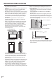
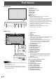
Part Names nFront view 1. LCD panel 2. Brightness sensor 3. Remote control sensor 4. Input switch 5. Power switch 6. Power LED 1 TIPS 2 nRear view 3 4 5 • Use a pointed object such as a pen tip to press the switches at the front of the monitor. • When you use the brightness sensor, you can automatically change the screen brightness according to lighting conditions and the surrounding brightness. (See page 24.
Part Names Remote control unit n 1 2 8 3 9 4 5 10 11 6 12 1. 2. 3. 4. 5. 6. 7. 8. 9. 10. 11. 12.
Connecting Peripheral Equipment 1. PC/AV HDMI input terminal • Use a commercially available HDMI cable (conforming to the HDMI standard). • Set HDMI of INPUT SELECT on the OPTION menu according to the device to be connected. • Select the audio input terminal to be used in PC HDMI or AV HDMI of AUDIO SELECT on the OPTION menu. When HDMI is selected, connection to the audio input terminal is unnecessary.
Connecting Peripheral Equipment (Example connection) PC/AV DVI-D output terminal PC/AV DVI-D input terminal TIPS Second monitor First monitor • Be sure to connect the + and - terminals and the left and right speakers properly. • Avoid short circuiting the + and - terminals. 12. Audio1 input terminals 13. Audio2 input terminals • Set the audio input terminal to be used in each input mode in AUDIO SELECT on the OPTION menu. PC/AV DVI-D input terminal 14.
Connecting Peripheral Equipment ■ Connection with the control kit (optional) Caution • When attaching the remote control sensor box, turn the main power switch OFF. • Except for the remote control sensor box connection cable, do not insert any other cable into the control kit terminal. Also, do not connect any connection cables that have been extended with commercially available cables. 1. Insert the remote control sensor box connection cable into the control kit terminal.
Preparing the Remote Control Unit Installing the batteries Remote control operation range 1. Press the cover gently and slide it in the direction of the arrow. Use the remote control unit at a distance of approx. 16.4 feet (5 m) from the remote control sensor with an angle of approx.10° from the center to the top/bottom/left/right of the sensor. Remote control sensor 2.
Connecting the Power Cord Caution • Use only the power cord supplied with the monitor. 1. Turn off the main power switch. 2. Plug the power cord (supplied) into the AC input terminal. 3. Plug the power cord (supplied) into the AC power outlet. 3 Main power switch 2 1 AC input terminal Power cord (Supplied) Binding Cables The cables connected to the terminals on the rear of the monitor can be fastened with the cable clamps.
Removing the Handles Handle spacers The handles can be removed. Remove the handle screws and remove the handles and handle spacers. Handle screws Caution • The handles, handle screws and handle spacers are for this monitor. Do not use them for any other devices. • When attaching the handles, perform the steps for removing the handles in reverse. Always use this monitor’s handles, handle spacers, and handle screws. Also, be sure the handles are attached securely.
Turning Power On/Off Caution TIPS • Turn on the monitor first before turning on the PC or playback device. Turning on the main power Main power switch • If the monitor is in the input signal standby mode and you press the POWER button on the remote control unit, the monitor enters standby mode. • You can turn on/off the monitor by pressing the power switch on the front panel of the monitor. • Setting the SCHEDULE flashes the power LED alternately in red and orange in standby mode.
Basic Operation 4. VOL +/- (Volume adjustment) Pressing or displays the VOLUME menu when the menu screen is not displayed. 1 VOLUME 2 3 15 Press or to adjust the volume of the sound. * If you do not press any buttons for about 4 seconds, the VOLUME menu automatically disappears. 4 5 5. BRIGHT +/- (Backlight adjustment) Pressing or displays the BRIGHT menu when the menu screen is not displayed. 7 BRIGHT 6 15 8 1. INPUT (Input mode selection) or The menu is displayed.
Basic Operation nSwitching the screen size Even when the screen size is changed, the display may remain the same depending on the input signal. WIDE ZOOM 1 PC input Displays image so it fills the entire screen. AV input An image with a 4:3 aspect ratio is stretched to fill the entire screen. PC input An image with a 4:3 aspect ratio is enlarged to fill the entire screen without changing the aspect ratio. The edges of the image may be cut off.
Menu Items Displaying the menu screen TIPS Video and audio adjustment and settings of various functions are enabled. This section describes how to use the menu items. See pages 22 to 26 for details of each menu items. Caution • Do not turn the main power switch off while the menu items are being displayed. Doing so may initialize the settings. • The menu will differ depending on the input mode. • The menu screen will close automatically if no operation is performed for about 15 seconds.
Menu Items Menu item details The menu will differ depending on the input mode. nSCREEN You can move the menu screen display position each time DISPLAY is pressed. AUTO (PC D-SUB/PC RGB) The CLOCK, PHASE, H-POS, and V-POS are automatically adjusted. Pressing performs adjustment. Use this automatic adjustment when you use the PC D-sub input terminal or PC RGB input terminals to display a PC screen for the first time or when you change the setting of the PC. (See page 29.
Menu Items USER Adjusts each item when the WHITE BALANCE is set to USER. R-CONTRAST.....Adjusts bright-toned red component. G-CONTRAST.....Adjusts bright-toned green component. B-CONTRAST.....Adjusts bright-toned blue component. R-OFFSET...........Adjusts dark-toned red component. G-OFFSET..........Adjusts dark-toned green component. B-OFFSET...........Adjusts dark-toned blue component. COPY TO USER Copies the value set for PRESET to the USER setting. MENU Select “ON” and then press .
Menu Items LANGUAGE Sets the display language for the menu screen. POWER ON DELAY You can delay the screen display after the monitor is turned on. The period can be set up to 60 seconds in units of one second. When this function is activated, the power LED flashes (at approx. 1 second interval) in orange. This function is disabled when 0 is specified. STANDBY MODE When STANDARD is selected, startup time from standby mode is reduced. Note, however that, more power will be consumed in standby mode.
Menu Items nOPTION DATE/TIME SETTING Set the date and time. Press to select the date or or to change the numerical and time, and press values. Set the date in “Month/Day/Year” order. Set the time on a 12-hour basis. (Factory default) DATE/TIME FORMAT Sets the date/time display format. DATE................... MM/DD/YYYY DD/MM/YYYY YYYY/MM/DD (YYYY: Year, MM: Month, DD: Day) TIME.................... Select 12- or 24-hour time. SCHEDULE (See page 28.
Menu Items nMULTI ENLARGE (See page 27.) Sets whether or not to use the enlarge function. ADVANCED (ENLARGE) ENLARGE H / ENLARGE V .......... Sets the number of screen splits (number of monitors) in the horizontal/vertical direction used for the enlargement. ENLARGE-POS .......... Specify the split screen to be displayed when the enlargement function is used. H-POS / V-POS .......... Adjust the horizontal/vertical position of the enlarged screen.
Menu Items nDual screen display nEnlarge You can display the screens of the PC input signal and AV input signal simultaneously. Set this function with “PIP MODES” in the PIP/PbyP menu. PIP A sub screen is displayed inside a main screen. Main screen Sub screen PbyP Main screen Sub screen PbyP2 Main screen Sub screen • You can align several monitors and integrate them into a single large screen to display. • Up to five monitors can be aligned in both the horizontal and vertical directions.
Menu Items nZOOM2 SPECIAL SETTING If you connect a laptop computer with any of the following screen resolutions and black bands appear around the screen, set ZOOM2 SPECIAL SETTING of INPUT SIGNAL on the OPTION menu to ON and then select ZOOM2 in the SIZE setting. This displays the area inside the black band.
Menu Items nADVANCED items (AV input) (See page 22 for additional Menu item details.) FLESH TONE Adjust the hue control. 3D-NR Reduce the noise of playback images on video. Setting a higher level reduces more noise. However, it may cause blurring on an image. MPEG-NR Reduce block noise caused by digital compression. 3D-Y/C (AV VIDEO) Specify whether to perform 3-dimension Y/C separation. If dot interference or cross-color is occurring in fast-motion scenes, selecting “OFF” may improve the image quality. C.
Initialization (Reset)/Functional Restriction Setting (FUNCTION) You can return the settings to their factory-preset values and restrict operations. SIZE until “F” is displayed in the upper left area 1. Press of the screen, then while “F” is being displayed, press , , , and in that order. FUNCTION ALL RESET ADJUSTMENT LOCK ADJUSTMENT LOCK TARGET RS-232C OSD DISPLAY LED TEMPERATURE ALERT STATUS ALERT POWER BUTTON CONTROLLER INPUT 1/1 OFF UNLOCKED ON1 ON LED OFF MONITOR END…[MENU] 2.
Controlling the Monitor with a PC (RS-232C) You can control this monitor from a PC via RS-232C (COM port) on the PC. You can also connect multiple monitors via a daisy chain by using a PC. By assigning ID numbers to each monitor (see page 33), you can make input mode selection/adjustment or can check the status of a specific monitor. Precautions when the PN-ZB01 (optional) is attached • To control the monitor via RS-232C, set RS-232C/LAN SELECT to RS-232C.
Controlling the Monitor with a PC (RS-232C) nResponse code format When RS-232C/LAN SELECT is set to LAN When a command has been executed correctly O K Return code (0DH, 0AH) Space (20H) SPC 0 0 1 ID number of responding monitor When a command has not been executed E R R Return code (0DH, 0AH) Return code (0DH, 0AH) Space (20H) R R SPC 0 0 • “ERR” is returned when there is no relevant command or when the command cannot be used in the current state of the monitor.
Controlling the Monitor with a PC (RS-232C) Advanced operation This section explains commands for daisy chain connection. The basic communication procedure is the same as in the “One-to-one connection with a PC” section. nCommands for ID control The command examples shown on this page assume the following connection and ID number set up. ID number: 1 ID number: 2 ID number: 3 ID number: 4 nID numbers You can assign a unique ID number to each monitor (see page 24).
Controlling the Monitor with a PC (RS-232C) IDLK ��������The parameter of this command sets the ID number of the monitor. The monitor is subject to all subsequent commands. Example: IDLK0002 WAIT OK Following commands are for the monitor ← with ID number: 2. ← 002 Searching for monitor with ID number: 2 Sets volume of monitor with ID ← number: 2 to 30.* WAIT ← Processing 002 VOLM0020 Sets volume of monitor with ID ← number: 2 to 20.
Controlling the Monitor with a PC (RS-232C) nRepeater control command Repeater control is achieved by setting the FOURTH CHARACTER of the parameter to “+”. Example: VOLM030 + ← Sets volume of all monitors to 30. In repeater control, responses are returned by all the connected monitors. If you want to determine that a value has been returned by a specific set, assign ID numbers to each monitor in advance.
Controlling the Monitor with a PC (RS-232C) RS-232C command table How to read the command table Command: Command field (See page 31.) Direction: W When the “Parameter” is set in the parameter field (see page 31), the command functions as described under “Control/Response Contents”. R The returned value indicated under “Reply” can be obtained by setting “????”, “ ?” or “???+” (repeater control) in the parameter field (see page 31). Parameter: Parameter field (See page 31.
Controlling the Monitor with a PC (RS-232C) SCREEN menu Function Command Direction Auto ASNC W CLOCK CLCK WR PHASE positioning size RESOLUTION RESET Parameter Reply Control/Response contents 1 When the input mode is PC D-SUB, PC RGB. 0-1200 0-1200 When the input mode is PC D-SUB, PC RGB. Varies depending on the signal. PHSE WR 0-63 Position of the longest direction HPOS WR 0-100 0-100 0-800 on PC D-SUB, PC RGB. Varies depending on the signal.
Controlling the Monitor with a PC (RS-232C) PICTURE menu Function Command Direction Auto AGIN W 1 When the input mode is PC D-SUB, PC RGB. ANALOG GAIN ANGA WR 0-127 0-127 When the input mode is PC D-SUB, PC RGB. ANALOG OFFSET ANOF WR 0-127 0-127 When the input mode is PC D-SUB, PC RGB.
Controlling the Monitor with a PC (RS-232C) AUDIO menu Function Command Direction Parameter Reply Control/Response contents TREBLE AUTR WR -5-5 BASS AUBS WR -5-5 -5-5 BALANCE AUBL WR -10-10 -10-10 RESET ARST W Command Direction OSD H-POSITION OSDH WR 0-100 0-100 OSD V-POSITION OSDV WR 0-100 0-100 SCREEN MOTION SCSV WR 0-4 0-4 *1 *2 (A) (B) -5-5 ○ ○ ○ - 3 SETUP menu Function MOTION TIME 1 MOTION TIME 2 Parameter Reply Control/Response contents MTIM WR 0-2
Controlling the Monitor with a PC (RS-232C) OPTION menu Function Command Direction Date/time setting DATE WR DATE DISPLAY FORMAT DTFT WR TIME DISPLAY FORMAT TMFT WR SCHEDULE SC01SC08 WR SCHEDULE BRIGHTNESS INPUT SELECT AUDIO SELECT SB01SB08 WR DVI DVSL BNC Parameter Reply AABBCCDDEE Control/Response contents AABBCCDDEE 0-2 0-1 ABCDEFFGGH 0-2 0: YYYY/MM/DD, 1: MM/DD/YYYY, 2: DD/MM/YYYY YYYY: Year, MM: Month, DD: Day 0-1 0: 24-HOUR TIME, 1: 12-HOUR TIME Schedule of a specified nu
Controlling the Monitor with a PC (RS-232C) MULTI menu Function Command Direction Parameter Reply Control/Response contents *1 ENLARGE ENLG WR 0-1 ENLARGE MODE EMAG WR 0-4 EMHV WR 11-55 11-55 1 x 1 (OFF) to 5 x 5 (“m x n” is expressed as “mn”, where m and n are the numbers of monitors specified for the longest direction and the shortest direction respectively.) IMAGE POSITION (M x N) EPHV WR 11-55 11-55 Specifies values in the order of IMAGE POSITION IN LONGEST/ SHORTEST DIRECTION.
Controlling the Monitor with a PC (RS-232C) PIP/PbyP menu Function Command Direction PIP MODES MWIN WR 0-3 PIP SIZE MPSZ WR 1-64 PIP POS The longest direction MHPS The shortest direction MVPS PIP POS LD+SD BATCH W Parameter Reply 0-100 0-100 R MPOS W 0-100 0-100,0-100 R PIP BLEND MWBL WR PIP SOURCE MWIP WR 0-3 0: OFF, 1: PIP, 2: PbyP, 3: PbyP2 1-64 0-100 R W Control/Response contents Specify the position in MPOSxxxyyy format.
Controlling the Monitor with a PC (RS-232C) Others Function Command Direction SCREEN SIZE (PC) WIDE WR 1-5 1-5 1: WIDE, 2: NORMAL, 3: Dot by Dot, 4: ZOOM1, 5: ZOOM2 SCREEN SIZE (AV) WIDE WR 1-5 1-5 1: WIDE, 2: ZOOM1, 3: ZOOM2, 4: NORMAL, 5: Dot by Dot VOLUME VOLM WR 0-31 MUTE MUTE WR 0-1 MODEL INF1 R SERIAL NO INFORMATION SRNO R BRIGHT VLMP WR TEMPERATURE SENSOR DSTA R Parameter Reply Control/Response contents 0-31 0-1 0: OFF, 1: ON ○ ○ ○ *2 (A) (B) - Value ● Value
Controlling the Monitor with a PC (LAN) When the PN-ZB01 (optional) is attached, your monitor can be connected to a LAN allowing you to control it from a PC on the LAN. You can also configure the monitor to send e-mail notification when it has a problem. The connection requires a commercially available LAN cable (UTP cable, Category 5, straight through). Network (LAN) Settings to connect to a LAN Set the monitor’s IP address and subnet mask to match the settings of your LAN.
Controlling the Monitor with a PC (LAN) ■ To set from a PC When the monitor is connected to a PC, LAN settings can be configured via PC. Set up process (1) Connect your monitor to a PC (2) Specify the PC’s IP address (3) Configure the monitor’s LAN settings 7. Temporarily change the IP address and subnet mask. To access the monitor as it is shipped from the factory, set as follows. • IP Address: 192.168.150.1 • Subnet Mask: 255.255.255.
Controlling the Monitor with a PC (LAN) 7. Specify the “DHCP CLIENT”, “IP ADDRESS”,etc. Controlling with a PC ■ Basic operation You use Internet Explorer on a PC on the LAN to control the monitor. 1. Launch Internet Explorer on the PC. 2. In the “Address” box, type “http://” followed by your monitor’s IP address followed by “/”, then press the Enter key. You can confirm the IP address with the DISPLAY function.
Controlling the Monitor with a PC (LAN) ■ INFORMATION Information about this monitor appears. ■ ADJUSTMENT You can adjust these settings which are also available on the monitor’s menu. • SCREEN (See page 22.) • PICTURE (See page 22.) • PICTURE (ADVANCED) (See page 29.) • AUDIO (See page 23.) • SETUP (See page 23.) • OPTION (See page 25.) • SCHEDULE (See page 28.) • MULTI (See page 26.) • PIP/PbyP (See page 26.) • FUNCTION (See page 30.
Controlling the Monitor with a PC (LAN) ■ NETWORK (LAN SETUP) This screen allows you to set the settings necessary when the monitor is connected to a LAN. DHCP CLIENT If your LAN has a DHCP server and you wish to obtain an address automatically, change this setting to “ON”. To set the address manually, set this to “OFF”. IP ADDRESS If the DHCP CLIENT is set to “OFF”, specify an IP address. SUBNET MASK If the DHCP CLIENT is set to “OFF”, specify the subnet mask.
Controlling the Monitor with a PC (LAN) ■ NETWORK (GENERAL) This screen allows you to specify the general LAN settings. MONITOR NAME Specify a name for this monitor as it should appear on the Internet Explorer screen. AUTO LOGOUT TIME Specify the time (in minutes) to elapse before automatically disconnecting this monitor from the network. Specify in minutes from 1 to 65535. A value of ‘0’ will disable this function. DATA PORT Specify the TCP port number to use for exchanging data with the monitor.
Controlling the Monitor with a PC (LAN) ■ MAIL (RECIPIENT) This screen allows you to specify the recipients of the e-mail sent periodically or when the monitor has an error. RECIPIENT E-MAIL ADDRESSES Specify the e-mail addresses to send error notification e-mail to. CONDITION Specify the conditions to send mails. When you check PERIODICAL, specify the date and time to send the mails in the PERIODICAL setting. CONFIRMATION Sends test e-mail.
Controlling the Monitor with a PC (LAN) ■ SNMP You can configure settings related to SNMP. Caution • After you set SNMP, click [Switch the main power of monitor off and on now.] or turn off the monitor and then turn it on again with the main power switch. When the monitor restarts, wait about 30 seconds and then start the next operation. • If the IP address is changed while the SNMP function is operational, turn off the monitor and then turn it on again with the main power switch.
Troubleshooting If you are experiencing any problem with your display, before calling for service, please review the following troubleshooting tips. There is no picture or sound. • Is the power cord disconnected? (See page 16.) • Is the main power switch off? (See page 18.) • Is the monitor in standby mode (the power LED illuminating in orange)? • Make sure correct input mode is selected. (See page 19.) • If any external equipment is connected, make sure the equipment is operating (playing back).
Troubleshooting The Power LED is flashing in red and green alternately. When “TEMPERATURE” is displayed in the corner of the screen. • When the internal temperature of the monitor rises excessively, the brightness of the backlight decreases automatically in order to prevent high-temperaturerelated problems. When this occurs, “TEMPERATURE” is displayed on the screen and the Power LED flashes red and green alternately. (When TEMPERATURE ALERT is set to OSD & LED. This varies depending on the setting.
Specifications nPN-A601 Product Specifications Model LCD component Max. resolution Max. colors Pixel pitch Viewing angle Screen active area inch Computer input signal Sync signal PN-A601 60" Class [60 inch (152.5cm) diagonal] TFT LCD (pixels) 1920 x 1080 Approx. 1.06 billion colors 0.692 mm (H) × 0.692 mm (V) 176° right/left/up/down (contrast ratio ≥ 10) (mm) 52-5/16 x 29-7/16 (1329.1 x 747.6) Digital (DVI 1.0 standard-compliant), Analog RGB (0.
Specifications nDimensional Drawings Note that the values shown are approximate values. Unit: inch [mm] 52-3/8 [1331] 5-13/16 [147] 2-7/8 [73] 3-9/16 [90] 49-1/8 [1247] VESA holes * 54-1/8 [1374] 7-7/8 [200] 7-7/8 [200] 3-15/16 3-15/16 [100] [100] 7-7/8 [200] 31-1/4 [793] Opening height (29-5/8 [753]) Opening width (52-1/2 [1334]) When mounting the monitor, be sure to use a wall-mount bracket that complies with the VESA-compatible mounting method.
Specifications nCompatible signal timing (PC) Screen resolution VESA 640 × 480 800 × 600 848 × 480 1024 × 768 1152 × 864 1280 × 768 1280 × 800 1280 × 960 1280 × 1024 Wide US TEXT Sun 1360 × 768 1400 × 1050 1440 × 900 1600 × 1200*1 1680 × 1050 1920 × 1200*1 1280 × 720 1920 × 1080 720 × 400 1024 × 768 1152 × 900 1280 × 1024 1600 × 1000 Hsync Vsync Dot frequency 31.5kHz 37.9kHz 37.5kHz 35.1kHz 37.9kHz 48.1kHz 46.9kHz 31.0kHz 48.4kHz 56.5kHz 60.0kHz 67.5kHz 47.8kHz 60.3kHz 49.7kHz 60.0kHz 64.
Specifications nCompatible signal timing (AV) Screen resolution 1920 × 1080p 1920 × 1080i 1280 × 720p 720 × 576p 720 × 480p 640 × 480p(VGA) 720(1440) × 576i 720(1440) × 480i Frequency 24Hz 50Hz 59.94Hz 60Hz 50Hz 59.94Hz 60Hz 50Hz 59.94Hz 60Hz 50Hz 59.94Hz 60Hz 59.94Hz 60Hz 50Hz 59.
Specifications nPC/AV DVI-D (DVI-D 24 pin) No. 1 input terminal pins Function No. Function No. Function 13 N.C. 1 TMDS data 2+ 11 TMDS clock shield 2 TMDS data 2+ 14 +5V 2 TMDS data 2 shield 12 TMDS clock- 3 TMDS data 2/4 shield 15 GND 3 TMDS data 2- 13 CEC 4 N.C. 16 Hot-plug detection 4 TMDS data 1+ 14 N.C. 5 N.C.
Mounting Precautions (For SHARP dealers and service engineers) • When installing, removing or moving the monitor, ensure that this is carried out by at least 2 people. • Be sure to use a wall-mount bracket designed or designated for mounting the monitor. • This monitor is designed to be installed on a concrete wall or pillar. Reinforced work might be necessary for some materials such as plaster / thin plastic board / wood before starting installation.
PN-A601 Mu EN11J(1)