PN-CD701 LCD MONITOR OPERATION MANUAL
IMPORTANT: To aid reporting in case of loss or theft, please record the product’s model and serial numbers in the space provided. The numbers are located in the rear of the product. Model No.: Serial No.: U.S.A.
IMPORTANT INFORMATION WARNING: TO REDUCE THE RISK OF FIRE OR ELECTRIC SHOCK, DO NOT EXPOSE THIS PRODUCT TO RAIN OR MOISTURE. CAUTION RISK OF ELECTRIC SHOCK DO NOT OPEN CAUTION: TO REDUCE THE RISK OF ELECTRIC SHOCK, DO NOT REMOVE COVER. NO USER-SERVICEABLE PARTS INSIDE. REFER SERVICING TO QUALIFIED SERVICE PERSONNEL.
DEAR SHARP CUSTOMER Thank you for your purchase of a SHARP LCD product. To ensure safety and many years of trouble-free operation of your product, please read the Safety Precautions carefully before using this product. SAFETY PRECAUTIONS Electricity is used to perform many useful functions, but it can also cause personal injuries and property damage if improperly handled. This product has been engineered and manufactured with the highest priority on safety.
SAFETY PRECAUTIONS (Continued) 19. Batteries — Incorrect use of batteries may cause the batteries to burst or ignite. A leaky battery may corrode the equipment, dirty your hands or spoil your clothing. In order to avoid these problems, make sure to observe the precautions below: • Use the specified batteries only. • Install the batteries with due attention to the plus (+) and minus (-) sides of the batteries according to the instructions in the compartment. • Do not mix old and new batteries.
TIPS AND SAFETY INSTRUCTIONS - The TFT color LCD panel used in this monitor is made with the application of high precision technology. However, there may be minute points on the screen where pixels never light or are permanently lit. Also, if the screen is viewed from an acute angle there may be uneven colors or brightness. Please note that these are not malfunctions but common phenomena of LCDs and will not affect the performance of the monitor.
MOUNTING PRECAUTIONS • This product is for use indoors. • A mounting bracket compliant with VESA specifications is required. • Since the monitor is heavy, consult your dealer before installing, removing or moving the monitor. • Mounting the monitor on the wall requires special expertise and the work must be performed by an authorized SHARP dealer. You should never attempt to perform any of this work yourself.
Contents IMPORTANT INFORMATION.............................................3 DEAR SHARP CUSTOMER...............................................4 SAFETY PRECAUTIONS...................................................4 TIPS AND SAFETY INSTRUCTIONS................................6 MOUNTING PRECAUTIONS.............................................7 Supplied Components......................................................9 System Requirements......................................................9 Part Names.......
Supplied Components If any components are missing, please contact your dealer. Liquid Crystal Display Monitor: 1 Power cord: 1 HDMI cable: 1 USB Type C cable (26.2 feet [8 m]): 1 USB Type C extend cable: 1 CD-ROM: 1 Setup Manual: 1 Touch pen: 1 USB A to B cable (for touch back): 1 Cable clamp: 1 Camera: 1 Knurled screw (M3): 2 USB A to B cable (for camera): 1 S/PDIF cable: 1 3.
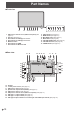
Part Names nFront view 1 2 3 4 5 6 7 1. USB port for external source (USB 3.0 compliant) (See page 13.) 2. Pen Tray (See page 17.) 3. LED indicator for USB Type C 1 source 4. LED indicator for USB Type C 2 source 5. Windows button 6. LED indicator for HDMI 7. LED indicator for Wireless LAN nRear view 15 35 8 2 8. 9. 10. 11. 12. 13. 14. 9 10 11 12 13 INPUT button (See page 21.) MENU button (See page 21.) MIC MUTE button (See page 21.) MUTE button (See page 21.) VOLUME DOWN button (See page 21.
Part Names 24. 25. 26. 27. 28. 29. 30. 31. 32. 33. 34. 35. 36. HDMI input terminal (See page 12.) Vents AC input terminal (See page 15.) Main power switch (See page 16.) USB Type C output terminal (See page 13.) USB port for storage expansion (USB 3.0 compliant) (See page 13.) LAN 2 terminal (See page 13.) Line out Audio output terminal (See page 12.) LAN 1 terminal (See page 13.) USB port for IoT sensor hub/USB devices (See page 12.) USB port for IoT sensor hub/USB devices (See page 12.
Connecting Peripheral Equipment nRear view 14 13 12 17 16 5 1 6 2 9 4 7 3 8 10 11 nFront view 15 Caution • Be sure to turn off the main power switch and disconnect the plug from the power outlet before connecting/ disconnecting cables. Also, read the manual of the equipment to be connected. • Be careful not to confuse the input terminal with the output terminal when connecting cables.
Connecting Peripheral Equipment 8. LAN 2 terminal • You can connect to the Internet by connecting a commercially available LAN cable between this terminal and a network. 9. LAN 1 terminal • By connecting this terminal to a network, you can connect an external device connected via USB to the network. 10. USB port for storage expansion (USB 3.0 compliant) • You can expand the storage used by the main system on this terminal by inserting a commercially available USB storage drive. 11.
Mounting an IoT sensor hub It is possible to mount an IoT sensor hub in the following position. 1. Attach the supplied IoT sensor hub mounting brackets (L/R) to the IoT sensor hub with the supplied IoT sensor hub screws (M3) (x2). 2. Fix the IoT sensor hub mounting brackets (L/R) to this monitor with supplied knurled screws (M3) (x2). * The IoT sensor hub mounting brackets fit into the recess of this monitor.
Connecting the Power Cord Caution • Use only the power cord supplied with the monitor. Main power switch 1. Turn off the main power switch. 2. Plug the power cord (supplied) into the AC input terminal. 3. Plug the power cord (supplied) into the power outlet. 1 1 AC input terminal 2 Power cord (Supplied) 3 For power outlet Preparing the Remote Control Unit Installing the batteries Remote control operation range 1. Place your finger on the part marked with the ▲, and then pull the cover off.
Turning Power On/Off nOperations after first power-on Caution • Turn on the monitor first before turning on the computer or playback device. • When switching the main power switch or the POWER button off and back on, always wait for at least 5 seconds. A short interval may result in a malfunction. • To keep the performance, put the monitor in the Power off state once a day. When the monitor is turned on for the first time after being shipped from the factory, the setting screen will be displayed.
Touch Pen Pen Eraser TIPS • Incorrect operation may result if your finger is too close to the tip of the pen. • Hold the touch pen with your bare hand. The screen will not respond if you wear a glove. • When multiple touch pens are used, touch positions and touch pen information (color, thickness, etc.) may become interchanged, and lines may break. - When touched simultaneously. - When touch pens are moved near each other. • Do not press the pen tip on other than the screen. This may cause malfunctioning.
Touch action Touch action Touch actions that can be used with this monitor differ according to operating system and application. The functions of touch actions are also different. For details, check operating system Help and the application’s support documentation. Operating system Windows 8.
Touch action Drag-and-drop Same action as drag-and-drop with a mouse. Touch the screen with your finger/touch pen and move without lifting. When you have finished the movement, lift your finger/ touch pen. nFinger actions Zoom Use in a screen that is capable of enlargement/reduction. Touch the screen with two fingers and move your fingers closer together to reduce the view, or apart to enlarge the view. Flicks Flick your finger/touch pen in the direction of the function you want to use.
Touch action Rotate Use this action in a screen that is capable of image rotation. Touch the center point of the rotation with one finger. While holding that finger still, move another finger in the desired direction of rotation. Move another finger in the desired direction of rotation With one finger touching TIPS • The screen may not respond correctly in the following cases: - Touch gesture is too quick. - The distance between the two points is too short. - The two points intersect.
Basic Operation Button Operation IoT accessories Operation 1. Camera module Camera module build with camera and Mic array. Which provide conference video function. Camera 6 5 4 3 2 IoT sensor Hub 1 1. POWER button See page 16. 2. VOLUME DOWN / UP buttons 2.1 No device connection Controlling this monitor volume up/down. 2.2 Device connection Controlling input device volume up/down. (Windows only. Must be connected with a USB cable.) 3. MUTE button 3.
Basic Operation Using the remote control unit (option) 1. POWER When “Operation Mode” is set to “Mode1” Press the POWER button to turn the power OFF (standby mode). 1 When “Operation Mode” is set to “Mode2” When you press the POWER button, the backlight will be turned off. 2. MUTE Turns off the volume temporarily. Press the MUTE button again to turn the sound back to the previous level. 3. VOLUME +/- (Volume adjustment) Pressing + or - displays the VOLUME menu. Press + or - to adjust the volume.
Menu Items Displaying the menu 1. Home screen The Home Screen is the default screen that users will see when they launch this monitor. Dashboard Button Displays the measurement results of the IoT sensor. (Temperature, Humidity, CO2 Levels, TVOC Levels, Motion) Home Button The Home button can be tapped at any time to get the user back to the home screen. Back Button 2. Action panel Input Button It will allow users to go back inside apps and also within the menu.