PN-Y555 PN-Y475 PN-Y425 LCD MONITOR OPERATION MANUAL
IMPORTANT: To aid reporting in case of loss or theft, please record the product’s model and serial numbers in the space provided. The numbers are located in the rear of the product. Model No.: Serial No.: U.S.A.
IMPORTANT INFORMATION WARNING: TO REDUCE THE RISK OF FIRE OR ELECTRIC SHOCK, DO NOT EXPOSE THIS PRODUCT TO RAIN OR MOISTURE. CAUTION RISK OF ELECTRIC SHOCK DO NOT OPEN CAUTION: TO REDUCE THE RISK OF ELECTRIC SHOCK, DO NOT REMOVE COVER. NO USER-SERVICEABLE PARTS INSIDE. REFER SERVICING TO QUALIFIED SERVICE PERSONNEL.
DEAR SHARP CUSTOMER Thank you for your purchase of a SHARP LCD product. To ensure safety and many years of trouble-free operation of your product, please read the Safety Precautions carefully before using this product. SAFETY PRECAUTIONS Electricity is used to perform many useful functions, but it can also cause personal injuries and property damage if improperly handled. This product has been engineered and manufactured with the highest priority on safety.
SAFETY PRECAUTIONS (Continued) 19. Batteries — Incorrect use of batteries may cause the batteries to burst or ignite. A leaky battery may corrode the equipment, dirty your hands or spoil your clothing. In order to avoid these problems, make sure to observe the precautions below: • Use the specified batteries only. • Install the batteries with due attention to the plus (+) and minus (-) sides of the batteries according to the instructions in the compartment. • Do not mix old and new batteries.
IMPORTANT SAFETY INSTRUCTIONS 1) Read these instructions. 2) Keep these instructions. 3) Heed all warnings. 4) Follow all instructions. 5) Do not use this apparatus near water. 6) Clean only with dry cloth. 7) Do not block any ventilation openings. Install in accordance with the manufacturer’s instructions. 8) Do not install near any heat sources such as radiators, heat registers, stoves, or other apparatus (including amplifiers) that produce heat.
TIPS AND SAFETY INSTRUCTIONS - The TFT color LCD panel used in this monitor is made with the application of high precision technology. However, there may be minute points on the screen where pixels never light or are permanently lit. Also, if the screen is viewed from an acute angle there may be uneven colors or brightness. Please note that these are not malfunctions but common phenomena of LCDs and will not affect the performance of the monitor.
MOUNTING PRECAUTIONS • This product is for use indoors. • A mounting bracket compliant with VESA specifications is required. • Since the monitor is heavy, consult your dealer before installing, removing or moving the monitor. • Mounting the monitor on the wall requires special expertise and the work must be performed by an authorized SHARP dealer. You should never attempt to perform any of this work yourself.
Contents IMPORTANT INFORMATION.............................................3 DEAR SHARP CUSTOMER...............................................4 SAFETY PRECAUTIONS...................................................4 IMPORTANT SAFETY INSTRUCTIONS............................6 TIPS AND SAFETY INSTRUCTIONS................................7 MOUNTING PRECAUTIONS.............................................8 Supplied Components......................................................9 Part Names.......................
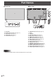
Part Names nFront view nRear view 7 6 16 17 1 18 19 20 21 8 2 3 4 9 10 5 11 1. 2. 3. 4. 5. LCD panel Remote control sensor (See page 16.) Input switch (See page 19.) Power button (See page 17.) Power LED (See page 17.) Caution 10 12 13 14 15 6. USB flash drive cover (See page 15.) 7. Vents 8. Speakers 9. AC input terminal (See page 14.) 10. Main power switch (See page 17.) 11. HDMI input terminal (See page 12.) 12. DVI-D input terminal (See page 12.) 13.
Part Names nRemote control unit 1 2 7 3 8 4 9 10 5 1. Signal transmitter 2. POWER button (See page 17.) 3. MUTE button (See page 19.) 4. VOL +/- buttons (See page 19.) BRIGHT +/- buttons (See page 19.) Cursor control ( / / / ) buttons 5. DISPLAY/Red button (See page 19.) 6. MODE/Green button (See page 19.) 7. INPUT button (See page 19.) 8. MENU button (See page 19.) 9. ENTER button (See page 19.) 10. RETURN button (See page 19.) 11.
Connecting Peripheral Equipment 4 9 10 5 8 6 1 Caution • Be sure to turn off the main power switch and disconnect the plug from the power outlet before connecting/ disconnecting cables. Also, read the manual of the equipment to be connected. • Be careful not to confuse the input terminal with the output terminal when connecting cables. Accidentally reversing cables connected to the input and output terminals may cause malfunctions and the other problems.
Connecting Peripheral Equipment 5. Audio1 input terminal • Use an audio cable without resistance. 6. Audio2 input terminals 7. DVI-D output terminal • When the input mode is set to DVI-D, the video of the DVI-D input can be output to an external device. • Outputting HDCP-encrypted video requires an external device which supports HDCP. • This terminal allows the daisy chain connection of up to 5 monitors by connecting the monitors to each other through the DVI-D input terminal of each monitor.
Connecting the Power Cord Caution • Use only the power cord supplied with the monitor. 1. Turn off the main power switch. 2. Plug the power cord (supplied) into the AC input terminal. 3. Plug the power cord (supplied) into the AC power outlet. For power outlet Main power switch 3 1 2 Power cord (Supplied) AC input terminal Binding Cables [PN-Y555] The cables connected to the terminals on the rear of the monitor can be fastened with the cable clamp.
Setting the USB flash drive cover 1. Insert the USB flash drive into the USB port. 2. Attach the USB flash drive cover and secure with the provided screw. USB port USB flash drive cover screw TIPS • If the USB flash drive will be attached, use a USB flash drive with dimensions no greater than 1-15/16 inch (50 mm) (L) × 13/16 inch (20 mm) (W) × 1/2 inch (12 mm) (H). Affixing the Stand Hole Protection Covers After installing the monitor, affix the stand hole protection covers as necessary. 1.
Preparing the Remote Control Unit Installing the batteries Remote control operation range 1. Press the cover gently and slide it in the direction of the arrow. The operation range of the remote control unit is approx. 16.4 feet (5 m) at an angle of approx 10° from the center to the top/ bottom/right/left of the remote control sensor. 2. See the instructions in the compartment and put in the supplied batteries (R-6 (“AA” size) x 2) with their plus (+) and minus (-) sides oriented correctly. 3.
Turning Power On/Off Caution • Turn on the monitor first before turning on the PC or playback device. Turning power on/off Press the POWER button to turn the power ON/OFF. Turning on the main power When the main power is turned on, the power LED lights. Wait until the screen is displayed. POWER button Status Main power switch Caution • The main power must be turned on/off with the main power switch.
Turning Power On/Off nDate/time setting • If the time has not been set, such as when the monitor is first turned on, set the date and time in DATE/TIME SETTING of the SETUP menu. Be sure to set the date and time. TIPS • Set the time on a 24-hour basis. • The clock stops if the main power remains off for about 1 week.* (*Approximate time. The actual time varies depending on the state of the monitor.
Basic Operation 1 2 5. BRIGHT +/- (Brightness adjustment) or displays the BRIGHT menu when the Pressing menu screen is not displayed. 3 4 5 31 6 7 8 9 Press or to adjust the brightness. * If you do not press any buttons for about 30 seconds, the BRIGHT menu automatically disappears. 6. ENTER Confirms the setting. 10 7. RETURN Returns to the previous screen. 1. INPUT (Input mode selection) The menu is displayed. Press or to select the input ENTER mode, and press to enter.
Basic Operation nSwitching the screen size Even when the screen size is changed, the display may remain the same depending on the input signal. NORMAL Displays image so it fills the screen without changing the aspect ratio of the input signals. WIDE Displays image so it fills the entire screen. Dot by Dot Displays the dots of the input signals as the corresponding dots on the screen.
Playing the Files in a USB Flash Drive Playing files A USB flash drive can be inserted in the monitor to display images, videos, and music in the USB flash drive on the monitor. For information on USB flash drive, see page 12. You can play the specified image/video/ audio files in a USB flash drive. Auto playback The image files or video files in a USB flash drive can be automatically played. Create a folder with the name “autoplay” in the top level of the USB flash drive.
Playing the Files in a USB Flash Drive n Selecting files to be played (3) Movie Select a file with 1. Insert the USB flash drive into a USB port on the monitor. (See page 12.) or 4. Select an icon with (4) (3) and press (2) or Select a file with or . • To move to the file genre menu, press . ENTER , . (4) Music 2. Change an input mode to [USB]. (See page 19.) 3. Press , . . or and To narrow down audio files, select with ENTER .
Playing the Files in a USB Flash Drive Operations during play Settings n Image files n Settings when the file list is displayed Operation is possible using the buttons below. DISPLAY ENTER / MODE : Play/Pause a slideshow. Select an item with . and press ENTER . Shuffle : End playback. Select whether or not playback is shuffled during a slideshow or continuous playback. n Video files Operation is possible using the buttons below. : Move back about 10 seconds.
Playing the Files in a USB Flash Drive n Settings during play Press MENU during playback. Configure the desired setting with , , , , and ENTER Options “Settings when the file list is displayed” (See page 23.) or “Status” (only when playing video) appears. Picture and sound COLOR MODE Changes the color mode on the screen. VOLUME Adjust the volume. SIZE Changes the screen size of video.
Menu Items Displaying the menu screen nMenu screen display Video and audio adjustment and settings of various functions are enabled. This section describes how to use the menu items. See pages 26 to 31 for details of each menu item. Caution • Do not turn the main power switch off while the menu items are being displayed. Doing so may initialize the settings. • This cannot be displayed when the input mode is USB. Change an input mode to other than USB before performing these operations.
Menu Items Menu item details The menu will differ depending on the input mode. nSCREEN AUTO (D-SUB[RGB]) The H/V-POS, etc. are automatically adjusted. H/V-POS Adjust the horizontal and vertical position of the image. SIZE Changes the screen size. The screen size can also be changed using a remote control unit. (See page 19.) ZOOM (HDMI[AV]/D-SUB[COMPONENT]/D-SUB[VIDEO]) Enlarge and display part of the image.
Menu Items nAUDIO BASS Adjusts the volume of bass-level sound. TREBLE Adjusts the volume of treble-level sound. RESET Resets the values of the AUDIO menu items to the factory preset values. ENTER . Select “ON” and then press nSETUP DATE/TIME SETTING to select the date and time, and press or or to change the numerical values. Set the date and time. Press Set the time on a 24-hour basis. SCHEDULE (See page 30.) You can turn the power on/off at a specified time.
Menu Items POWER ON DELAY You can delay the screen display after the monitor is turned on. The period can be set up to 60 seconds in units of 1 second. When this function is activated, the power LED flashes (at approx. 1 second interval) in orange. AUTO INPUT CHANGE Specify whether to change inputs automatically. When ON is selected and no signal is present in the selected input mode, AUTO INPUT CHANGE automatically changes the selected mode to another mode where a video signal is present.
Menu Items nEnlarge • You can align several monitors and integrate them into a single large screen to display. • Up to 5 monitors can be aligned in both the horizontal and vertical directions. • Each monitor displays enlarged views of separated images. (Example) Horizontal direction: 2 monitors Vertical direction: 2 monitors Horizontal direction: 3 monitors Vertical direction: 2 monitors Setting procedure Set using MULTI in the SETUP menu. 1. Set ENLARGE to ON. 2. Select ADVANCED. 3.
Menu Items nSCHEDULE (6) PLAYLIST SETTING You can set the time to switch the motion on and off. A file in a USB flash drive can also be played at a specified time. Set “INPUT” in SCHEDULE to “USB”, and create a play list. Set this function with SCHEDULE in the SETUP menu. (See page 27.) This only appears when INPUT is set to [USB]. Use to create a playlist for automatic display/playback of files in a USB flash drive. • Image files and video files can be combined in the same playlist.
Menu Items Caution • Do not switch off the main power after setting the SCHEDULE. • Set the time for both power-on and power-off. The time for either only cannot be set. Schedule ON and then OFF only take place in power standby mode and signal standby mode. • Specify the correct date and time. (See page 27.) SCHEDULE does not function unless the date and time are specified. • Check regularly that the set date and time are correct.
Controlling the Monitor with a PC (RS-232C) You can control this monitor from a PC via RS-232C (COM port) on the PC. You can also connect multiple monitors via a daisy chain by using a PC. By assigning ID numbers to each monitor (see page 33), you can make input mode selection/adjustment or can check the status of a specific monitor. TIPS • To control the monitor via RS-232C, set STANDBY MODE to STANDARD.
Controlling the Monitor with a PC (RS-232C) nResponse code format When a command has been executed correctly O K Return code (0DH, 0AH) A response is returned after a command is executed.
Controlling the Monitor with a PC (RS-232C) nCommands for ID control The command examples shown on this page assume the following connection and ID SETTING. ID number: 1 ID number: 2 ID number: 3 ID number: 4 IDST ��������. A monitor receiving this command sets its own ID number in the parameter field. Example: IDST0001 OK 001 ← The ID number of this monitor is set to 1. IDLK ��������The parameter of this command sets the ID number of the monitor. The monitor is subject to all subsequent commands.
Controlling the Monitor with a PC (RS-232C) nRepeater control This system has a function to allow setting of multiple monitors connected in a daisy chain using a single command. This function is called repeater control. You can use Repeater control function without assigning ID numbers. [Example] Set 1 Set 2 Set 3 Set 4 * If monitors are connected as shown above, you can execute a command like “Set all monitors’ input settings to D-SUB”.
Controlling the Monitor with a PC (RS-232C) RS-232C command table How to read the command table Command: Command field (See page 32.) Direction: W When the “Parameter” is set in the parameter field (see page 32), the command functions as described under “Control/Response Contents”. R The returned value indicated under “Reply” can be obtained by setting “????”, “ ?” or “???+” (repeater control) in the parameter field (see page 32). Parameter: Parameter field (See page 32.
Controlling the Monitor with a PC (RS-232C) SETUP menu Command Direction DATE/TIME SETTING Function DATE WR ID SETTING IDST ID NO.SETTING W Parameter Reply AABBCCDDEE Control/Response contents AABBCCDDEE 0-25 Sets the monitor’s ID number. (“0” means “no ID number”.) 0-25 Returns the monitor’s ID number. R ID NO. SETTING (ONCE) IDSL W 1-25 ID NO.
Controlling the Monitor with a PC (LAN) Your monitor can be connected to a LAN allowing you to control it from a PC on the LAN. The connection requires a commercially available LAN cable (UTP cable, Category 5, straight through). Network (LAN) Settings to connect to a LAN Set the monitor’s IP address and subnet mask to match the settings of your LAN. The settings depend on the configuration of your LAN. Ask your LAN administrator for details. ■ To set on the monitor Set the LAN SETUP options.
Controlling the Monitor with a PC (LAN) Command-based control You can control the monitor using RS-232C commands (see page 36) via terminal software and other appropriate applications. Read the manual for the terminal software for detailed instructions. (1) Connect the PC to the monitor. 1. Specify the IP address and data port number (fixed at “10008”), and connect the PC to the monitor. When connection has been established successfully, [ Login:] is returned as response. 2.
Troubleshooting If you are experiencing any problem with your display, before calling for service, please review the following troubleshooting tips. There is no picture or sound. • Is the power cord disconnected? (See page 14.) • Is the main power switch off? (See page 17.) • Is the monitor in standby mode (the power LED illuminating in orange)? (See page 17.) • Make sure correct input mode is selected. (See page 19.
Troubleshooting The Power LED is flashing in red and green alternately. • When the internal temperature of the monitor rises excessively, the brightness of the backlight decreases automatically in order to prevent high-temperature-related problems. When this occurs, the Power LED flashes red and green alternately. • If the internal temperature rises further, the monitor automatically enters standby mode. (The Power LED continues flashing red and green alternately.
Specifications nProduct Specifications Model LCD component PN-Y555 PN-Y475 PN-Y425 47" Class [46-15/16 inch 42" Class [42 inch 55" Class [54-5/8 inch (106.7cm) diagonal] (119.3cm) diagonal] (138.8cm) diagonal] TFT LCD TFT LCD TFT LCD Max. resolution (pixels) 1920 x 1080 Max. colors Approx. 1.06 billion colors Pixel pitch 0.630 mm (H) × 0.542 mm (H) × 0.485 mm (H) × 0.630 mm (V) 0.542 mm (V) 0.
Specifications nDimensional Drawings Note that the values shown are approximate values.
Specifications nPower management This monitor conforms to VESA DPMS and DVI DMPM. Both your video card and computer must support the same standard in order for the monitor’s power management function to work.
Specifications nCompatible signal timing (PC) Screen resolution VESA 640 × 480 800 × 600 1024 × 768 1280 × 768 1280 × 800 1280 × 960 1280 × 1024 Wide US TEXT 1360 × 768 1400 × 1050 1440 × 900 1600 × 1200* 1920 × 1200* 1280 × 720 1366 x 768 1920 × 1080 720 × 400 Hsync Vsync Dot frequency 31.5kHz 37.9kHz 37.5kHz 35.1kHz 37.9kHz 48.1kHz 46.9kHz 48.4kHz 56.5kHz 60.0kHz 47.8kHz 49.7kHz 60.0kHz 64.0kHz 80.0kHz 47.7kHz 65.3kHz 55.9kHz 75.0kHz 74.0kHz 44.7kHz 47.7kHz 67.5kHz 31.
Specifications nDVI-D input (DVI-D 24 pin) No. terminal pins Function Function No. Function No. Function TMDS data 2- 13 N.C. 1 TMDS data 2+ 11 TMDS clock shield 2 TMDS data 2+ 14 +5V 2 TMDS data 2 shield 12 TMDS clock- 3 TMDS data 2/4 shield 15 GND 3 TMDS data 2- 13 CEC 4 N.C. 16 Hot-plug detection 4 TMDS data 1+ 14 N.C. 5 N.C.
Specifications nDVI-D output (DVI-D 24 pin) No. nRS-232C output (D-sub 9 pin) terminal pins Function No. Function No. Function terminal pins No. Function 1 TMDS data 2- 13 N.C. 1 N.C. 6 N.C. 2 TMDS data 2+ 14 +5V 2 Received data 7 N.C. 3 TMDS data 2/4 shield 15 GND 3 Transmitted data 8 N.C. 4 N.C. 16 Hot-plug detection 4 N.C. 9 N.C. 5 N.C. 17 TMDS data 0- 5 GND 6 DDC clock 18 TMDS data 0+ 7 DDC data 19 TMDS data 0/5 shield 8 N.C. 20 N.C.
Mounting Precautions (For SHARP dealers and service engineers) • When installing, removing or moving the monitor, ensure that this is carried out by at least 2 people. • Be sure to use a wall-mount bracket designed or designated for mounting the monitor. • This monitor is designed to be installed on a concrete wall or pillar. Reinforced work might be necessary for some materials such as plaster / thin plastic board / wood before starting installation.
PN-Y555-Y475-Y425 Mu EN14G(2)