
NUJD450

SIM02E-003E
4
mark. If dirt build-up becomes excessive, clean the glass
surface with water only.
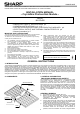
INSTALLATION INSTRUCTIONS -PHOTOVOLTAIC MODULES-
1. INSTALLATION
Mounting Using Clips:
The PV modules can be mounted with clips (clamps) as defined in
the following. Note that the mounting clips should meet the required
dimensions as defined in the Figure1. Note that the CLIP CENTER
POSITION (e) from the module corner should be located in the
range as specified in the Annex. All clips shall hold the module frame
completely within their width. Please be aware that the module under
heavy load would get serious deflection which could cause cell
cracks that affects power degradation. The PV module must be
supported on the array system and must overlap the array rail by at
least 10mm.
Mounting Using Frame Bolt Holes:
The modules may be fastened to a support using the bolt holes in
the bottom of the frames at any of locations shown in Annex. The
module should be fastened with four (4) M8 bolts. Recommended
torque is 12.5 Nm.
2. ELECTRICAL INSTALLATION INSTRUCTION
Cable characteristics
Conductor size: 4.0mm
2
, Cable type: XLPE cable (H1Z2Z2-K)
Maximum DC voltage: 1.5kV
Ambient temperature: -40°C to +90°C
Maximum conductor temperature: 120 °C
PV module configuration (Recommend)
# Maximum series configuration: please refer to Table 1
# Maximum parallel configuration: (Parallel connection of
each string shall be conducted with following two options.
Any other parallel connections are prohibited.)
a) Case of using the diodes; 1 diode per maximum 2
parallel strings (Connect a diode or more in series for
every string or every 2 parallel strings for protection of
PV module from reverse current over load.)
b) Case of using the fuses; 1 fuse per every string (Connect
a fuse for every single string for protection of PV module
from reverse current over load.)
Connection cables requirement
The PV module shall be mated to the same connectors;
Type: C1 (System voltage 1,500V)
Brand: Solargiga Energy Holdings Limited
In case connectors will be replaced by qualified personnel
according the mounting instructions of the manufacturer of
the new connectors, the guarantees on the module itself,
will remain valid according the applicable terms.
3. WARNING
Keep all PV MODULES and
electrical CONNECTORS clean &
dry before installation.
4. Disposal
Dispose PV modules properly. For
Information about the proper
disposal, contact your local
recycling site.
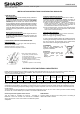
ELECTRICAL OUTPUT AND THERMAL CHARACTERISTICS
Rated electrical characteristics are within ±10 percent of the indicated values of Voc, Isc and +5/-0 percent of Pmax, under STC
(standard test conditions) (irradiance of 1000W/m
2
, AM 1.5 spectrum, and a cell temperature of 25°C (77°F)).
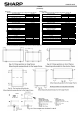
T able-1. E lectrical characteristics (at S T C )
Model
name
Max imum
Power
(Pmax )
Tolerance
Open-Curcuit
Voltage
(Voc)
Short-Circuit
Current
(Isc)
Voltage at point
of max . Power
(Vmpp)
Current at point
of max. Power
(Impp)
Max imum
system voltage
Over-Current
Protection
Class for protection
against elecrical
shock
Maximum series
configuration(*)
NU-JD450 450W +5%/-0% 49.35V 11.61A 41.56V 10.83A 1,500V 20A
Ⅱ
25
* The maximum series number of modules depends on the local conditions. These values are calculated under the condition of Voc at -40 °C.
Under normal conditions, a PV module is likely to experience conditions that produce more current and/or voltage than reported
at Standard Test Conditions. Accordingly, the values of Isc and Voc marked on this PV module should be multiplied by a factor
of 1.25 when determining component voltage ratings, conductor capacities, fuse sizes and size of controls connected to the PV
module output.
The PV module has been qualified in an environmental temperature range of -40 °C to +40 °C and up to 100% relative humidity
as well as rain, and the altitude up to 2,000m in accordance with IEC61730.
Class for protection against electric shock
This PV module is classified as “Class Ⅱ ” according to
IEC61730. These PV modules are intended for installation
where general user access and contact to insulated live parts is
anticipated.
FIRE RATING
This PV module is rated as “Fire safety class C” according to
IEC61730-2:2004 or UL790.
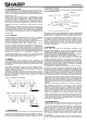
Figure1. Clips (Clamps) requirement
1) Clip: Al alloy, 3 mm Min. thickness
2) Catch length (50 mm Min.)
3) Covering depth (7 mm Min. on the frame)
4) Supporting depth (10 mm Min.)
5) Frame (applicable to all frame sections)
6) Array rail
(applicable to parallel or crossed mounting)