
NUJD450

SIM02E-003E
5
Annex
(normative)
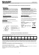
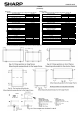
【Test load】 【Design load】
Table.A1(-1) Test load using clamps on long frames (see Fig. A1)
Table.A1 Design load using clamps on long frames (see Fig. A1)
clip center position
clip center position
(L, Lc: mm)
downward force
upward force
(L, Lc: mm)
downward force
upward force
300 < L <400 (by 4 clips)
plus 2 clips on Lc = 979
5,400Pa 2,400Pa
300 < L <400 (by 4 clips)
plus 2 clips on Lc = 979
3,600Pa 1,600Pa
L = 300 (by 4 clips)
3,600Pa
2,400Pa
L = 300 (by 4 clips)
2,400Pa
1,600Pa
300 < L <527 (by 4 clips)
2,400Pa
2,400Pa
300 < L <527 (by 4 clips)
1,600Pa
1,600Pa
0 < L <527 (by 4 clips)
1,200Pa
1,200Pa
0 < L <527 (by 4 clips)
800Pa
800Pa
Table.A2(-1) Test load using clamps on short frames (see Fig. A2)
Table.A2 Design load using clamps on short frames (see Fig. A2)
clip center position
clip center position
(S: mm)
downward force
upward force
(S: mm)
downward force
upward force
0< S <262
900Pa*
900Pa*
0< S <262
600Pa
600Pa
Table.A3(-1) Test load using Bolt Holes (see Fig. A3)
Table.A3 Design load using Bolt Holes (see Fig. A3)
bolts & nuts
bolts & nuts
(position of using holes)
downward force
upward force
(position of using holes)
downward force
upward force
4points at "c" holes
2,400Pa
2,400Pa
4points at "c" holes
1,600Pa
1,600Pa
4points at "b" holes
2,400Pa
2,400Pa
4points at "b" holes
1,600Pa
1,600Pa
2points at "c" & 2 points at opposite "b" holes
2,400Pa
2,400Pa
2points at "c" & 2 points at opposite "b" holes
1,600Pa
1,600Pa
Table.B1(-1) Test load using clamps on long & short frames (see Fig. B1)
Table.B1 Design load using clamps on long & short frames (see Fig. B1)
clip center position
clip center position
(L, S: mm)
downward force
upward force
(L, S: mm)
downward force
upward force
100< L <527 , 0< S <262
1,200Pa*
1,200Pa*
100< L <527 , 0< S <262
800Pa
800Pa
0< L <527 , 0< S <262
900Pa*
900Pa*
0< L <527 , 0< S <262
600Pa
600Pa
Table.B2(-1) Test load using clamps on long & short frames (see Fig. B2)
Table.B2 Design load using clamps on long & short frames (see Fig. B2)
clip center position
clip center position
(L, S: mm)
downward force
upward force
(L, S: mm)
downward force
upward force
L = 527 , S = 262
1,200Pa*
1,200Pa*
L = 527 , S = 262
800Pa
800Pa
0< L <527 , 0< S <262
900Pa*
900Pa*
0< L <527 , 0< S <262
600Pa
600Pa
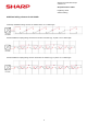
* Test procedure according to IEC 61215-2:2016. The test results are based on internal evaluation.
note: The Test load has been calculated with a safety factor of 1.5 from the design load.
test load
design load
test load
design load
test load
design load
test load
design load
test load
design load
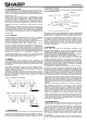
1. Spring washer 2. Washer
Material: Stainless steel Material: Stainless steel
Diameter: M8 8.2/15.4mm Diameter: M8 8.5/15.5mm
Thickness: 2 mm (reference value) Thickness: 1.6 mm (reference value)
3. Bolt 4. Nut
Material: Stainless steel Material: Stainless steel
Size: M8 Size: M8
Diameter: M8 x 20mm
Fig. A
3
: The components for BOLT & NUT