
Operation Manual SETUP MANUAL


7
E
ENGLISH
n
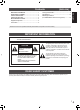
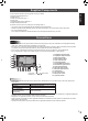
Connection with RS-232 cable
If you connect the monitor in a daisy chain using RS-232
cables, settings are copied from the primary (main unit) to the
secondary (expansion unit) and operation from the primary
can perform operation for all monitors.
Connect the RS-232 cables in order, starting with the rst
monitor (primary monitor).
If monitors are connected in a different order they may not be
operable.
RS-232 straight cable
(commercially available)
First monitor: primary
Second monitor: secondary
Third monitor: connects to
secondary RS-232C input terminal
RS-232C
input
terminal
RS-232C
output terminal
RS-232C
output
terminal
Connect in the same way to the third and subsequent
monitors.
Up to 25 monitors can be connected. (Depending on the
length of the cable used and the surrounding environment.)
Setting each ID No. in the monitor is required.
Perform operation with the rear side buttons on the primary
monitor. If you set AUTO ASSIGN ID No., located in the menu
of the monitor to ON, the ID No. will be automatically assigned
in order from the primary.
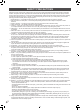
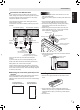
n
Mounting the control kit (optional) on the
monitor
If performing operation of the monitor with the remote control
unit, the PN-ZR01A control kit (optional) is required.
Attach the remote control sensor box as shown in the following
illustration.
For the monitor in
landscape orientation
For the monitor in
portrait orientation
Caution
• When attaching the remote control sensor box, turn the
main power switch OFF.
• Connect the monitors together in a daisy chain with RS-232
cable.
1. Peel off the sticker (
) that has been afxed to the
monitor’s remote control sensor box mounting hole.
2. Secure the mounting bracket by inserting the mounting
screw into the monitor’s remote control sensor box
mounting hole.
3. Adjust the angle of the remote control sensor box, and
secure it with the xing screw, so that it may accurately
receive signals from the remote control unit.
Angle adjustment
Mounting bracket
Mounting screw
Fixing screw
Remote control
sensor box
Remote control sensor
box mounting hole
4. Insert the remote control sensor box connection cable into
the control kit terminal.
Connection
cable
Control kit terminal
Remote control
sensor box
Installing the batteries
1. Press the cover gently and slide it in the direction of the
arrow.
2. See the instructions in the compartment and put in the
batteries (R-6 (“AA” size) x 2) (supplied with the PN-ZR01A
(optional)) with their plus (+) and minus (-) sides oriented
correctly.
3. Close the cover.
Connections