DATA PROJECTOR MODEL XG-PH80W-N XG-PH80X-N SETUP MANUAL Setting up the Screen..........................................................................2 Screen Size and Projection Distance ................................................3 Connecting Pin Assignments ...........................................................14 RS-232C Specifications and Commands ........................................16 Setting up the Projector Network Environment .............................18 1.
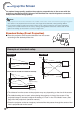
Setting up the Screen For optimal image quality, position the projector perpendicular to the screen with the projector 's feet flat and level. Doing so will eliminate the need for Keystone correction and provide the best image quality. Note • The projector lens should be centered in the middle of the screen. If the horizontal line passing through the lens center is not perpendicular to the screen, the image will be distorted, making viewing difficult.
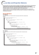
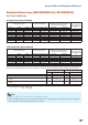
Screen Size and Projection Distance The projection screen size varies according to the distance from the lens of the projector to the screen. The optional lenses from Sharp are also available for specialized application. Please see your nearest Sharp Authorized Projector Dealer to details on all the lenses. (Refer to the lens operation manual when using a lens.) Install the projector so that projected images are projected onto the screen at the optimum size by referring to the table.
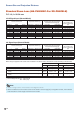
Screen Size and Projection Distance Standard Zoom Lens (AN-PH818EZ: For XG-PH80W-N) F1.7-1.9, f = 26-34 mm 16:10 Signal Input (Normal Mode) Picture (Screen) size Diag.
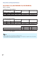
Screen Size and Projection Distance Standard Zoom Lens (AN-PH818EZ: For XG-PH80X-N) F1.7-1.9, f = 26-34 mm 4:3 Signal Input (Normal Mode) Picture (Screen) size Distance from the lens center to the center of the image [W] Distance from the lens center to the bottom of the image [H] Projection distance [L] Diag. [F] Width Height Minimum [L1] Maximum [L2] 500" (1270 cm) 1016 cm (400'') 762 cm (300'') 18.1 m (59' 4") 23.9 m (78' 4") 300" (762 cm) 610 cm (240'') 457 cm (180'') 10.9 m (35' 7") 14.
Screen Size and Projection Distance Fixed Wide Lens (AN-PH808EX: For XG-PH80W-N) F2.0, f = 11.4 mm 16:10 Signal Input (Normal Mode) Picture (Screen) size Diag. [F] 200'' (508 cm) 150'' (381 cm) 100'' (254 cm) 50'' (127 cm) Width Height 431 cm (170'') 269 cm (106'') 323 cm (127'') 202 cm (79'') 215 cm (85'') 135 cm (53'') 108 cm (42'') 67 cm (26'') Projection distance [L] 3.3 m (10' 11") 2.5 m (8' 2") 1.7 m (5' 6") 0.
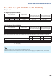
Screen Size and Projection Distance Fixed Wide Lens (AN-PH808EX: For XG-PH80X-N) F2.0, f = 11.4 mm 4:3 Signal Input (Normal Mode) Picture (Screen) size Diag. [F] 200'' (508 cm) 150'' (381 cm) 100'' (254 cm) 50'' (127 cm) Width Height 406 cm (160'') 305 cm (120'') 305 cm (120'') 229 cm (90'') 203 cm (80'') 152 cm (60'') 102 cm (40'') 76 cm (30'') Projection distance [L] 3.1 m (10' 4") 2.4 m (7' 9") 1.6 m (5' 2") 0.
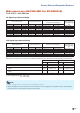
Screen Size and Projection Distance Wide-zoom Lens (AN-PH814EZ: For XG-PH80W-N) F1.81-2.29, f = 19.3-25.8 mm 16:10 Signal Input (Normal Mode) Picture (Screen) size Diag. [F] 500" (1270 cm) 300" (762 cm) 200" (508 cm) 100" (254 cm) 80" (203 cm) 70" (178 cm) 60" (152 cm) 40" (102 cm) Distance from the lens center to the bottom of the image [H] Projection distance [L] Width Height Minimum [L1] Maximum [L2] 1077 cm (424") 673 cm (265") 14.3 m (47' 0") 19.3 m (63' 3") 646 cm (254") 404 cm (159") 8.
Screen Size and Projection Distance Wide-zoom Lens (AN-PH814EZ: For XG-PH80X-N) F1.81-2.29, f = 19.3-25.8 mm 4:3 Signal Input (Normal Mode) Picture (Screen) size Diag.
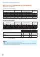
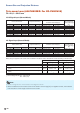
Screen Size and Projection Distance Tele-zoom Lens (AN-PH823EZ: For XG-PH80W-N) F2.1-2.9, f = 32-63 mm 16:10 Signal Input (Normal Mode) Picture (Screen) size Diag. [F] 500" (1270 cm) 300" (762 cm) 200" (508 cm) 150" (381 cm) 100" (254 cm) 80" (203 cm) 60" (152 cm) 40" (102 cm) Distance from the lens center to the bottom of the image [H] Projection distance [L] Width Height Minimum [L1] Maximum [L2] 1077 cm (424") 673 cm (265") 23.9 m (78' 5") 47.7 m (156' 6") 646 cm (254") 404 cm (159") 14.
Screen Size and Projection Distance Tele-zoom Lens (AN-PH823EZ: For XG-PH80X-N) F2.1-2.9, f = 32-63 mm 4:3 Signal Input (Normal Mode) Picture (Screen) size Diag.
Screen Size and Projection Distance Tele-zoom Lens (AN-PH845EZ: For XG-PH80W-N) F2.2-3.1, f = 63.5-117.4 mm 16:10 Signal Input (Normal Mode) Picture (Screen) size Diag.
Screen Size and Projection Distance Tele-zoom Lens (AN-PH845EZ: For XG-PH80X-N) F2.2-3.1, f = 63.5-117.4 mm 4:3 Signal Input (Normal Mode) Picture (Screen) size Diag.
Connecting Pin Assignments COMPUTER/COMPONENT input and COMPUTER/COMPONENT output Terminals: mini D-sub 15 pin female connector 6 1 10 5 11 15 COMPUTER Input/Output Pin No. Signal 1. Video input (red) 2. Video input (green/sync on green) 3. Video input (blue) 4. Not connected 5. Not connected 6. Earth (red) 7. Earth (green/sync on green) 8. Earth (blue) 9. Not connected 10. GND 11. Not connected 12. Bi-directional data 13. Horizontal sync signal: TTL level 14. Vertical sync signal: TTL level 15.
Connecting Pin Assignments RS-232C Cable recommended connection: D-sub 9 pin female connector 5 9 1 6 Pin No. 1. 2. 3. 4. 5. 6. 7. 8. 9. Signal CD RD SD ER SG DR RS CS CI Pin No. 1. 2. 3. 4. 5. 6. 7. 8. 9. Signal CD RD SD ER SG DR RS CS CI Note • Depending on the controlling device used, it may be necessary to connect Pin 4 and Pin 6 on the controlling device (e.g. computer). Projector Pin No. 4 5 6 4 3 Pin No. 1. 2. 3. 4.
RS-232C Specifications and Commands Computer control A computer can be used to control the projector by connecting an RS-232C serial control cable (cross type, commercially available) to the projector. (See page 24 of the projector's operation manual for connection.) Communication conditions Set the serial port settings of the computer to match that of the table. Signal format: Conforms to RS-232C standard.
RS-232C Specifications and Commands Commands Example: When turning on the projector, make the following setting.
Setting up the Projector Network Environment This section describes the basic procedure for using the projector via the network. If the network is already constructed, the projector's network settings may need to be changed. Please consult your network administrator for assistance with these settings. You can make network settings both on the projector and on the computer. The following procedure is for making settings on the computer. Network settings on the computer 1.
Setting up the Projector Network Environment 1. Connecting the Projector to a Computer Establishing a one-to-one connection from the projector to a computer. Using a commercially available LAN cable (UTP cable, Category 5, cross-over type) you can configure the projector via the computer. 1 Disconnect the computer's LAN cable from the existing network.
Setting up the Projector Network Environment 2. Setting an IP Address for the Computer The following describes how to make settings in Windows Vista®. 1 Log on the network using the administrator's account for the computer. 2 Click “start”, and click “Control Panel”. 2 1 3 Click “View network status and tasks” of “Network and Internet”, and click “View status” in the new window. • This manual uses examples to explain the operations in Category View.
Setting up the Projector Network Environment 5 Click “Internet Protocol Version 4 (TCP/IPv4)”, and click the “Properties” button. 1 2 6 Confirm or change an IP address for the setup computer. 1 Confirm and note the current IP address, Subnet mask and Default gateway. Make sure to note the current IP address, Subnet mask and Default gateway as you will be required to reset them later. 2 Set temporarily as follows: IP address: 192.168.150.3 Subnet mask: 255.255.255.
Setting up the Projector Network Environment 3. Setting up a Network Connection for the Projector Settings for such items as the projector's IP address and subnet mask are compatible with the existing network. Set each item on the projector as follows. (See page 54 of the projector's operation manual for setting.) DHCP Client: Off IP Address: 192.168.150.002 Subnet Mask: 255.255.255.000 1 Start Internet Explorer (version 6.0 or later) on the computer, and enter “http://192.168.150.2/system.
Setting up the Projector Network Environment 3 Confirm that the values are set properly, and then click the “Apply” button. • Close the browser. • This completes the network settings. • After setting items, wait for about 15 seconds and then re-access. • Change the IP address of the setting computer back to its original address, which you have noted down in Step 6-1 on page 21, and then connect the computer and the projector to the network.
Controlling the Projector via LAN After connecting the projector to your network, enter the projector IP address in “Address” on Internet Explorer (version 6.0 or later) using a computer on the network to start a setup screen that will enable control of the projector via the network. Controlling the Projector Using Internet Explorer Complete connections to external equipment before starting the operation. (See pages 21-25 of the projector's operation manual.) Complete the AC cord connection.
Controlling the Projector via LAN Controlling the Projector and Confirming the Projector Status On this screen, you can perform projector control or confirm the projector status.
Controlling the Projector via LAN Making General Settings for the Network Enter “http://XXX.XXX.XXX.X/lanconf. html” (for “XXX.XXX.XXX.X”, enter the IP address set by the procedure on page 22) in “Address” on Internet Explorer (version 6.0 or later) using a computer on the network to display the “Projector LAN Configuration” screen. On this screen, you can make general settings relating to the network. ■ DOMAIN Items Description Host Name Setting a hostname.
Operating the Projector Using the PJLinkTM Protocol The projector conforms with the PJLinkTM standard Class 1. The commands to be used in controlling the projector by the PJLinkTM protocol are as shown below.
Troubleshooting Communication cannot be established with the projector When connecting the projector using serial-connection ? Check that the RS-232C terminal of the projector and a computer or the commercially available controller are connected correctly. ? Check that the RS-232C cable is a cross-over cable. ? Check that the RS-232C port setting for the projector corresponds to the setting for the computer or the commercially available controller.
Troubleshooting ? Take the following steps for checking the network settings for the computer. 1. Open a command prompt. • In the case of Windows® 2000: click “start” ➔ “Programs” ➔ “Accessories” ➔ “Command Prompt” in order. • In the case of Windows® XP, Windows Vista®: click “start” ➔ “All Programs” ➔ “Accessories” ➔ “Command Prompt” in order. 2. After launching the command prompt, enter the command “ipconfig”, and press the “Enter” key.
Troubleshooting ? Check if the “TCP/IP” protocol is operating correctly using the “PING” command. Also, check if an IP address is set. 1. Open a command prompt. • In the case of Windows® 2000: click “start” ➔ “Programs” ➔ “Accessories” ➔ “Command Prompt” in order. • In the case of Windows® XP, Windows Vista®: click “start” ➔ “All Programs” ➔ “Accessories” ➔ “Command Prompt” in order. 2. After launching the command prompt enter a command “PING”. Entry example C:\>ping XXX.XXX.XXX.XXX “XXX.XXX.XXX.
Dimensions 15 11/64 (385) Units: inches (mm) 1 3 /32 (99) 1 29 3 7/16 (87) 7 41/64 (194) 4 /4 (108) /8 (3) 4 13/64 (106.5) 19 57/64 (505) 9 61/64 (252.5) 9 61/64 (252.5) 5 11/32 (135.7) 8 49/64 (222.5) 4 59/64 (125) 8 49/64 (222.5) 4 59/64 (125) 3 1 /16 (30) 4 13/64 (106.5) M4 M4 4 (101.5) 5 29/64 (138.5) 2 15/64 (56.
Dimensions Projector and Lens Dimensions [When AN-PH818EZ is installed] Unit : inches (mm) 1 3/32 (27.7) [When AN-PH808EX is installed] 15 11/64 (385) 7 /64 (2.8) Unit : inches (mm) /64 3 7/16 (87) 61 15 11/64 (385) (24.2) 0 (0) [When AN-PH823EZ is installed] 3 7/16 (87) Unit : inches (mm) 9 /32 15 11/64 (385) (7) 13 /64 [When AN-PH814EZ is installed] 3 7/16 (87) (5) Unit : inches (mm) 7 /64 (2.