OPERATION MANUAL MODE D’EMPLOI MANUAL DE MANEJO MANUAL DE OPERAÇÃO FRANÇAIS XV-Z17000 PROJECTOR PROJECTEUR PROYECTOR PROJETOR ENGLISH XV-Z17000 ESPAÑOL PORTUGUÊS SHARP CORPORATION Printed in China Imprimé en Chine Impreso en China Impresso na China TINS-E929WJZZ 11P01-CH-NM
SPECIAL NOTE FOR USERS IN THE U.K. The mains lead of this product is fitted with a non-rewireable (moulded) plug incorporating a 10A fuse. Should the fuse need to be replaced, a BSI or ASTA approved BS 1362 fuse marked or and of the same rating as above, which is also indicated on the pin face of the plug, must be used. Always refit the fuse cover after replacing the fuse. Never use the plug without the fuse cover fitted.
Before using the projector, please read this operation manual carefully. ENGLISH Introduction IMPORTANT • For your assistance in reporting the loss or theft of your Projector, please record the Serial Number located on the bottom of the projector and retain this information. • Before recycling the packaging, please ensure that you have checked the contents of the carton thoroughly against the list of “Supplied accessories” on page 9. WARNING: Model No.: XV-Z17000 Serial No.
INFORMATION This equipment has been tested and found to comply with the limits for a Class B digital device, pursuant to Part 15 of the FCC Rules. These limits are designed to provide reasonable protection against harmful interference in a residential installation. This equipment generates, uses, and can radiate radio frequency energy and, if not installed and used in accordance with the operation manual, may cause harmful interference to radio communications.
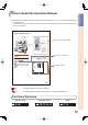
Introduction How to Read this Operation Manual The specifications are slightly different, depending on the model. However, you can connect and operate all models in the same manner. • In this operation manual, the illustration and the screen display are simplified for explanation, and may differ slightly from the actual display.
Contents Preparing Introduction How to Read this Operation Manual .............3 Contents ...........................................................4 IMPORTANT SAFEGUARDS............................6 Accessories .....................................................9 Part Names and Functions ...........................10 Using the Remote Control ............................13 Inserting the Batteries.......................................... 13 Usable Range ...................................................
Maintenance ..................................................59 Maintenance Indicators ................................60 Regarding the Lamp ......................................62 Lamp .................................................................. 62 Caution Concerning the Lamp............................. 62 Replacing the Lamp ............................................ 62 Removing and Installing the Lamp Unit................ 63 Resetting the Lamp Timer ...................................
IMPORTANT SAFEGUARDS CAUTION: Please read all of these instructions before you operate this product and save these instructions for later use. Electrical energy can perform many useful functions. This product has been engineered and manufactured to assure your personal safety. BUT IMPROPER USE CAN RESULT IN POTENTIAL ELECTRICAL SHOCK OR FIRE HAZARDS. In order not to defeat the safeguards incorporated in this product, observe the following basic rules for its installation, use and servicing. 1.
Caution concerning the lamp unit Potential hazard of glass particles if lamp ruptures. In case of lamp rupture, contact your nearest Sharp Authorized Projector Dealer or Service Center for replacement. See “Regarding the Lamp” on page 62. Caution concerning the setup of the projector For minimal servicing and to maintain high image quality, SHARP recommends that this projector be installed in an area free from humidity, dust and cigarette smoke.
Other connected equipment When connecting a computer or other audio-visual equipment to the projector, make the connections AFTER unplugging the power cord of the projector from the AC outlet and turning off the equipment to be connected. Please read the operation manuals of the projector and the equipment to be connected for instructions on how to make the connections.
Introduction Accessories Supplied accessories Remote control Two AA size batteries Two pairs of 3D Glasses*1 Power cord*2 (1) (2) For U.S. and Canada, etc. (6' (1.8 m)) For Europe, except U.K. (6' (1.8 m)) (3) (4) For U.K. and Singapore (6' (1.8 m)) For Australia, New Zealand and Oceania (6' (1.8 m)) *1 See pages 50 to 52 for details of the 3D Glasses and their accessories.
Part Names and Functions Numbers in refer to the main pages in this operation manual where the topic is explained. Projector 10 11 12 13 14 15 16 17 18 19 20 1 2 3 4 5 6 7 8 9 Front View 1 Exhaust vent 59 2 Zoom ring 15, 24 For enlarging/reducing the picture. 3 Focus ring 15, 24 For adjusting the focus. 4 Lens shutter 23, 28, 63 5 IR (infrared) emitter 52 Emits an infrared signal when 3D images are projected.
Introduction Projector (Rear View) 1 2 3 4 5 6 11 7 89 10 Using the Carrying Handle When transporting the projector, carry it by the carrying handle on the side. • Always close the lens shutter to prevent damage to the lens when transporting the projector. • Do not lift or carry the projector by the lens as this may damage the lens. Terminals 1 RS-232C terminal 22 Terminal for controlling the projector using a computer.
Part Names and Functions (Continued) Numbers in refer to the main pages in this operation manual where the topic is explained. Remote Control 1 ON button 14, 23 For turning the power on. 1 2 STANDBY button 15, 23 2 3 HDMI1, 2, COMPONENT, S-VIDEO, VIDEO, COMPUTER buttons 15, 27 3 For putting the projector into the standby mode. For switching to the respective input modes. 4 11 12 5 13 6 14 7 15 4 FREEZE button 28 For freezing images.
Introduction Using the Remote Control Inserting the Batteries 1 Pull down the tab on the cover and remove the cover towards the direction of the arrow. 2 Insert the supplied batteries and put back the cover. • Make sure the polarities correctly match the m and n marks inside the battery compartment. • When putting back the cover, be sure that the cover clicks in place and settles.
Quick Start This section provides an example showing how to connect the projector to video equipment that has an HDMI output terminal with a brief explanation of the steps from connection through to image projection. For details, see the pages suggested in each step. 3, 7 STANDBY/ON 7 STANDBY button 3 ON button 5 Input Mode button Select buttons 6 Zoom ring 5 INPUT button 6 Focus ring 6 Adjustment feet 1. Place the projector facing a screen Page 16 2.
4. Turn the video equipment on and start playback 5. Select the input mode Quick Start Playback Page 27 Press HDMI1 on the remote control to select “HDMI1” for the Input mode. HDMI1 YPbPr 1080P HDMI1 button • Press HDMI1, HDMI2, COMPONENT, S-VIDEO, VIDEO and COMPUTER on the remote control to switch the Input mode. • Press P or R to select your desired input mode when you press INPUT on the remote control or on the projector. 6. Adjust the projector angle, focus and zoom 1.
Setting Up the Projector Setting Up the Projector For optimal image quality, position the projector perpendicular to the screen with the projector’s feet flat and level. Note • The projector lens should be centered in the middle of the screen. If the horizontal line passing through the lens center is not perpendicular to the screen, the image will be distorted, making viewing difficult. • For optimal image, position the screen so that it is not in direct sunlight or room light.
Projection (PRJ) Mode The projector can use any of the 4 projection modes, shown in the diagram below. Select the mode most appropriate for the projection setting in use. (You can set the PRJ Mode in “SCR-ADJ” menu. See page 45.
Setting Up the Projector (Continued) Screen Size and Projection Distance When using a wide screen (16:9): In case of displaying the 16:9 picture on the whole of the 16:9 screen. Diag.
Samples of Cables for Connection • For more details of connection and cables, refer to the operation manual of the connecting equipment. • You may need other cables or connectors not listed below.
Connecting to Video Equipment Before connecting, be sure to unplug the power cord of the projector from the AC outlet and turn off the devices to be connected. After making all connections, turn on the projector and then the other devices. Connecting Equipment with HDMI Output Terminal to the HDMI Terminal on the Projector For video connection, use a cable that conforms to HDMI standards. Using cables that do not conform to HDMI standards may result in a malfunction.
Connecting to a Computer Ensure that the computer is the last device to be turned on after all the connections are made. Connecting to a Computer Using the RGB Cable Computer To COMPUTER/COMPONENT terminal To RGB output terminal RGB cable (commercially available) Connections Note • Refer to “Compatibility Chart” on page 70 for a list of computer signals compatible with the projector. Use with computer signals other than those listed may cause some of the functions not to work.
Controlling the Projector by a Computer When the RS-232C terminal on the projector is connected to a computer, the computer can be used to control the projector and check the status of the projector. When connecting to a computer using an RS-232C serial control cable Computer To RS-232C terminal To RS-232C terminal RS-232C serial control cable (cross type, commercially available) Note • The RS-232C function may not operate if your computer terminal is not correctly set up.
Turning the Projector On/Off Connecting the Power Cord Plug the supplied power cord into the AC socket on the rear of the projector. • The power indicator illuminates red, and the projector enters standby mode. Turning the Projector On Note that the connections to external equipment and power outlet should be done before performing the operations written below. (See pages 20 to 23.) Power cord (supplied) Info • English is the factory default language.
Image Projection Adjusting the Projected Image Zoom ring Focus ring 1 Adjusting the Focus You can adjust the focus with the focus ring on the projector. Rotate the focus ring to adjust the focus while watching the projected image. 2 Adjusting the Picture Size You can adjust the picture size using the zoom ring on the projector. Rotate the zoom ring to enlarge or shrink the picture size. 3 Adjusting the Height The height of the projector can be adjusted using the adjustment feet.
Keystone Correction This function can correct distortion of an image projected toward a spherical or cylindrical screen as well as trapezoidal distortion of an image on a flat screen and rotate the image at your arbitrary angle. KEYSTONE button Keystone When the image is projected either from the top or from the bottom towards the screen at an angle, the image becomes distorted trapezoidally. The function for correcting trapezoidal distortion is called Keystone Correction.
Image Projection (Continued) Sphere Rotation This function can correct distortion of an image projected toward a spherical or cylindrical screen. This function rotates the image at an arbitrary angle. 1 Press KEYSTONE to enter the keystone mode. 1 • The keystone mode list appears. (See page 25.) • The keystone mode list appears. (See page 25.) 2 Press P/R to select “SPHERE”, and then press ENTER. 2 3 Press P/R to select “ROTATION”, and then press ENTER. • The rotation menu guide appears.
Switching the Input Mode HDMI1, 2, COMPONENT, S-VIDEO, VIDEO, COMPUTER buttons Select the appropriate input mode for the connected equipment. Press HDMI1, 2, COMPONENT, S-VIDEO, VIDEO or COMPUTER on the remote control to select the input mode. IMAGE SHIFT button • When you press INPUT on the projector or on the remote control, the INPUT list appears. Press P/R to switch the INPUT mode.
Image Projection (Continued) Displaying the Black Screen Temporarily FREEZE button AUTO SYNC button PICTURE MODE button Close the lens shutter to temporarily display a black screen. Note • When you close the lens shutter, the projector will be turned off automatically after about 30 minutes. Freezing a Moving Image 1 Press FREEZE. 2 Press FREEZE again to return to the moving image from the currently connected device. • The projected image is frozen.
MAGNIFY buttons Displaying an Enlarged Portion of an Image IRIS 1, 2 buttons Graphs, tables and other portions of projected images can be enlarged. This is helpful when providing more detailed explanations. Adjustment buttons (P/R/O/Q) RETURN button 1 Press MAGNIFY on the remote control. MENU HIDE button ECO+QUIET button • Enlarges the image. • Pressing or MAGNIFY enlarges or reduces the projected image. Note ×1 ×2 Switching the Iris Setting . Press ×3 Press ×4 ×9 .
Image Projection (Continued) RESIZE button Resize Mode This function allows you to modify or customize the resize mode to enhance the input image. Press RESIZE on the projector or on the remote control. Note • The RESIZE function that can be selected varies depending on the input signal (resolution and vertical frequency). RESIZE button Resize Mode RESIZE Output screen image NORMAL The image is displayed with the original aspect ratio.
RESIZE Output screen image ZOOM 14:9 An image with a 14:9 aspect ratio and letterboxing is enlarged while maintaining the original aspect ratio. SMART ZOOM An image with a 4:3 aspect ratio is slightly enlarged. NATIVE The image is displayed according to the original input signal. About Copyrights • When using the RESIZE function to select an image size with a different aspect ratio to a TV program or video image, the image will look different from its original appearance.
Menu Bar Items The following shows the items that can be set in the projector. The selectable items vary depending on the selected input, input signals, or adjustment values. Items that cannot be selected will be grayed out.
“SIG-ADJ” menu Main menu SIG-ADJ Page 41 “SCR-ADJ” menu Main menu Sub menu Clock –150 Page 41 +150 Phase –30 Page 41 +30 H-Pos –150 Page 41 +150 V-Pos –60 Page 41 +60 SCR-ADJ Page 43 Reset Resolution Page 41 Auto Sync Page 41 On Off Signal Type Page 41 Auto RGB YPbPr Video System Page 42 Auto PAL SECAM NTSC4.43 NTSC3.
Menu Bar Items (Continued) “PRJ-ADJ” menu Main menu PRJ-ADJ Page 46 “3D MENU” Main menu Sub menu Auto Power Off Page 46 Economy Mode Page 46 One Touch Play Page 46 System Standby Page 46 On Off On Off On Off On Off Input Name Page 47 Demo Mode Page 47 On Off RS-232C 9600bps 38400bps 115200bps Page 47 Fan Mode Page 47 All Reset Page 47 Lamp Timer (Life) Page 47 -34 Normal High 3D MENU Page 55 Sub menu 3D Page 55 3D Format Page 55 On Off Auto Side By Side Top And Bottom 3D Depth Adjust –15 +15 P
Using the Menu Screen MENU button Adjustment buttons ('/"/\/|) ENTER button Adjustment buttons ('/"/\/|) ENTER button RETURN button MENU button RETURN button • Press RETURN to return to the previous screen when the menu is displayed. Menu Selections (Adjustments) • This operation can also be performed by using the buttons on the projector. 1 2 Example: “Picture” menu screen when COMPONENT is selected for input mode Press MENU. • The “Picture” menu screen for the selected input mode is displayed.
Using the Menu Screen (Continued) 3 Press ' or " to select the item you want to adjust. (Example: Selecting “Bright”) To adjust the projected image while viewing it Press ENTER. • The selected adjustment item (e.g. “Bright”) will be displayed at the bottom of the screen. • When ' or " is pressed, the next item will be displayed. (e.g. “Bright” is replaced with “Color” by pressing ".) Note • Press RETURN to return to the previous screen. 4 Press | or \ to adjust the item selected.
Picture Adjustment (“Picture” Menu) Picture SIG-ADJ Picture Mode Contrast Bright Color Tint Sharp Red Blue CLR Temp IRIS1 (Manual) IRIS2 (Auto) Eco+Quiet Advanced Reset Menu operation ⇒ Page 35 SCR-ADJ PRJ-ADJ Standard 0 0 0 0 0 0 0 0 High Brightness On Off IRIS2 (Auto) Eco+Quiet Advanced Gamma C.M.S.1 C.M.S.2 Bright Boost Film Mode Detail Enhance DNR MNR Reset 0 On Off Off Auto 0 Off Off SEL./ADJ. RETURN SEL./ADJ.
Picture Adjustment (“Picture” Menu) (Continued) Menu operation ⇒ Page 35 3 Switching the Iris Setting This function controls the quantity of the projected light and the contrast of the image. IRIS1 (Manual) Selectable items High Brightness High Contrast Description This mode gives priority to brightness over contrast. This mode gives priority to contrast over brightness. IRIS2 (Auto) This automatically selects the optimal contrast to match the image.
Menu operation ⇒ Page 35 • If there is data for the stored corrected color, the C.M.S. color adjustment screen is displayed. (Go to step 3.) C.M.S.1 Select Color Hue Saturation Value Effect C.M.S.1 Reset Return 3 Set or adjust each item in the C.M.S. color adjustment screen. C.M.S.1 Select Color Hue Saturation Value Effect C.M.S.1 Reset Return 0 0 0 0 On On SEL./ADJ. RETURN SEL./ADJ. RETURN 0 0 0 0 ENTER END ENTER END C.M.S.
Picture Adjustment (“Picture” Menu) (Continued) Menu operation ⇒ Page 35 8 Adjusting the Bright Boost Bright Boost uses Texas Instruments’ Bright Boost technology. The image becomes brighter while the color reproduction is kept at a high level. Selectable items On Description The Bright Boost function is activated. Off The Bright Boost function is not activated. w Mosquito Noise Reduction (MNR) The so-called Mosquito Noise (flickering) can be reduced.
Computer Image Adjustment (“SIG-ADJ” Menu) Menu operation ⇒ Page 35 The illustration shown here is for explanation and may be different from the actual on-screen display. *1 *2 Picture SIG-ADJ Clock Phase H-Pos V-Pos Reset Resolution Auto Sync Signal Type Video System Video Setup Dynamic Range SCR-ADJ 0 0 0 0 Signal Info : 1080P H : XX.X kHz/ SEL./ADJ. RETURN PRJ-ADJ On Auto Auto 0 IRE Auto V : XX.X Note • Avoid displaying computer patterns which repeat every other line (horizontal stripes).
Computer Image Adjustment (“SIG-ADJ” Menu) (Continued) Menu operation ⇒ Page 35 5 Setting the Video System The video input system mode is factory preset to “Auto”; however, a clear picture from the connected audio-visual equipment may not be received, depending on the video signal difference. In that case, switch the video signal. Selectable items Auto PAL SECAM *NTSC4.43 NTSC3.58 PAL-M PAL-N PAL-60 * When reproducing NTSC signals in PAL video equipment.
Adjusting the Projected Image (“SCR-ADJ” Menu) Menu operation ⇒ Page 35 The illustration shown here is for explanation and may be different from the actual on-screen display.
Adjusting the Projected Image (“SCR-ADJ” Menu) (Continued) Menu operation ⇒ Page 35 4 Auto V-Keystone Correction Select “Auto V-Keystone” in the “SCR-ADJ” menu and press ENTER. Vertical keystone correction is performed automatically. Select “Keystone Mode” in the “SCR-ADJ” menu and press ENTER. Then select a desired item among “Keystone”, “Sphere”, or “Rotation” and press ENTER. “Keystone” has been set as a default setting in which you can adjust “H-Keystone” and “V-Keystone”.
Menu operation ⇒ Page 35 Rotation This function can rotate the image at an arbitrary angle. O button Rotates the image counterclockwise. Q button Rotate the image clockwise. Rotation Correction 0 Reversing/Inverting Projected Images This function allows the projector to be used in a wider range of projection styles by allowing the image to be inverted to suit the projection environment (location).
Adjusting the Projector Function (“PRJ-ADJ” Menu) Menu operation ⇒ Page 35 The illustration shown here is for explanation and may be different from the actual on-screen display.
Menu operation ⇒ Page 35 Setting the Input Terminal Names (Input Name) Set the name of the input terminal (up to 14 alphanumerical characters). 1 Press P/R to select “Input Name” and then press ENTER. Picture Input name SIG-ADJ HDMI1 SCR-ADJ PRJ-ADJ HDMI1 5 Selecting the Transmission Speed (RS-232C) Make sure that both the projector and computer are set for the same baud rate. Selectable items 9600bps Description Transmission speed is slow. 38400bps 115200bps Transmission speed is rapid.
Enjoying 3D Image Viewing CAUTION: Before viewing 3D images, please read this section carefully. You can use special 3D Glasses to watch 3D-supported images on this projector. You can enjoy 3D images by viewing the video images through the 3D Glasses supplied with the projector or through optional 3D glasses sold separately.
Be careful of your surroundings when viewing 3D images. When you view 3D images, objects may appear at a distance closer or farther than the actual screen. This may cause you to misjudge the distance to the screen and possibly result in injury if you accidentally hit the screen or surrounding objects. As you get more comfortable viewing 3D images: Operate the “3D Depth Adjust” function to adjust the 3D effect. (See page 55.) Adjust the projected image to the most comfortable viewing size by zooming.
Enjoying 3D Image Viewing (Continued) Supplied Accessories for 3D Glasses Make sure the following accessories are provided with the 3D Glasses. Two sets of 3D Glasses are provided. 3D Glasses (×2) Pages 51 to 54 3D Glasses band * (×2) Page 52 Nose pad * (Large ×2, small ×2) Page 52 Glasses case (×2) Cleaning cloth (×2) Precision screwdriver (Phillips ×2, slotted ×2) Page 51 * Use the 3D Glasses band and nose pad as needed.
2 Before Using the 3D Glasses Before using the 3D Glasses for the first time, remove the insulating sheet attached to them. Remove the button cell battery. 1Place the tip of the slotted precision screwdriver into the opening between the button cell and the socket. 2Lift up the button cell while taking care not to get the screwdriver caught on the metal latch. 1 3 When the battery comes loose from the socket, pick it out with your fingers.
Enjoying 3D Image Viewing (Continued) Attaching the Nose Pad Attach either of the supplied nose pads as needed (such as when the glasses do not fit properly). The glasses come with a large and small nose pad. 1 1 2 Attaching the nose pad Removing the nose pad Note • When the battery power is low, the LED light blinks 6 times after the power is turned on. Switching to 3D and 2D Mode When viewing 3D images, you can press the power button to switch between 2D and 3D modes.
3D MENU button ENTER button Adjustment buttons ('/"/\/|) 3D MENU button 3D ON/OFF button Note • The screen may temporarily become black when the projector is trying to detect a 3D image signal and when switching from 3D to 2D mode. Viewing 3D Images Receiving a 3D Image Signal That Can Be Detected Automatically The image signal may contain a 3D identification signal. You can enable the projector to automatically detect the 3D image type by selecting “3D MENU” > “3D Auto Change”. (See page 55.
Enjoying 3D Image Viewing (Continued) Receiving a 3D Image Signal That Cannot Be Detected Automatically 1 Press 3D MENU. 2 Press P/R to select “3D”. 3 Press O/Q to select “On” or “Off”. • The 3D MENU screen is displayed. • To view in 3D mode: Select “On”, and then go to step 4. • Refer to “Setting the 3D Format Menu” on page 56 for supported 3D signals and formats. • If you select “Off”, the video source will be displayed with no conversion. 4 Press P/R to select “3D Format”, and then press ENTER.
3D Settings (“3D MENU”) The illustration shown here is for explanation and may be different from the actual on-screen display. 3D MENU 3D 3D Format 3D Depth Adjust IR Emitter Level 3D Auto Change Viewing Time Info Invert On Auto 0 Normal Yes Yes Note • Use this function to get more comfortable 3D images. • When you use this function, the 3D image will look different from its original 3D appearance. Keep this in mind while using this function.
Enjoying 3D Image Viewing (Continued) Setting the 3D Format Menu Select the appropriate 3D format for viewing while referring to the table below.
Note • These 3D Glasses can only be used with Sharp 3D-compatible LCD TVs or projectors that use infrared control technology. 3D Glasses lenses • Do not apply pressure to the lenses of the 3D Glasses. Also, do not drop or bend the 3D Glasses. • Do not scratch the surface of the lenses of the 3D Glasses with a pointed instrument or other object. Doing so may damage the 3D Glasses and reduce the quality of the 3D image. • Use only the cloth provided with the 3D Glasses to clean the lenses.
Enjoying 3D Image Viewing (Continued) Specifications – 3D Glasses Model AN-3DG10 Lens type Power supply Battery Battery life Dimension (W x H x D) Weight Liquid crystal shutter 3 V DC Lithium button battery (CR2032 × 1) Approx. 75 hours of continuous use 6 13/16 × 1 7/8 × 6 45/64 inch (172.7 × 47.5 × 170.0 mm) 0.2 lbs./65.0 g (including the lithium button battery) 50°F to 104°F (10°C to 40°C) (The 3D Glasses cannot operate fully at extreme high or low temperatures.
Maintenance Cleaning the projector Ensure that you have unplugged the power cord before cleaning the projector. The cabinet as well as the operation panel is made of plastic. Avoid using benzene or thinner, as these can damage the finish on the cabinet. Do not use volatile agents such as insecticides on the projector. Do not attach rubber or plastic items to the projector for long periods. The effects of some of the agents in the plastic may cause damage to the quality or finish of the projector.
Maintenance Indicators The warning lights (power indicator, lamp indicator and temperature warning indicator) on the projector indicate problems inside the projector. If a problem occurs, either the temperature warning indicator or the lamp indicator will illuminate red, and the projector will enter standby mode. After the projector has entered standby mode, follow the procedures given below.
Maintenance indicator Normal Abnormal Temperature Off Red blinks warning (On)/ indicator Red on (Standby) Lamp indicator Green on (Green blinks when the lamp is warming up.) Red on Red on (Standby) Power indicator Green on/ Red on Green blinks (Cooling) Red blinks Problem Cause The internal temperature is abnormally high. • Temperatures around the projector are high.
Regarding the Lamp Lamp It is recommended that the lamp (sold separately) be replaced when the remaining lamp life becomes 5% or less, or when you notice a significant deterioration in the picture and color quality. The lamp life (percentage) can be checked with the on-screen display. (See page 47.) Purchase a replacement lamp of type AN-K15LP from your place of purchase, nearest Sharp Authorized Projector Dealer or Service Center. IMPORTANT NOTE TO U.S.
Removing and Installing the Lamp Unit Warning! • Do not remove the lamp unit from the projector right after use. The lamp and parts around the lamp will be very hot and may cause burns or injury. Info • Do not touch the glass surface of the lamp unit or the inside of the projector. • To avoid injury to yourself and damage to the lamp, make sure you carefully follow the steps below. • Do not loosen other screws except for the lamp unit cover and lamp unit.
Regarding the Lamp (Continued) 4 Remove the lamp unit. 5 Insert the new lamp unit. 6 Securing screws • Loosen the securing screws from the lamp unit. Hold the lamp unit and pull it in the direction of the arrow. At this time, keep the lamp unit horizontal and do not tilt it. INTERLOCK • Press the lamp unit firmly into the lamp unit compartment. Fasten the securing screws. Warning! DO NOT DEFEAT THIS INTERLOCK Replace the lamp unit cover.
Connecting Pin Assignments COMPUTER/COMPONENT input Terminal : mini D-sub 15 pin female connector 11 1 6 15 5 10 COMPUTER Input COMPONENT Input Pin No. 1 2 3 4 5 6 7 8 9 10 11 12 13 14 15 Pin No.
RS-232C Specifications and Commands Computer control A computer can be used to control the projector by connecting an RS-232C cable (null modem, cross type, commercially available) to the projector. (See page 22 for connection.) Communication conditions Set the serial port settings of the computer as follows. Signal format: Conforms to RS-232C standard. Baud rate*: 9,600 bps / 38,400bps / 115,200bps Data length: 8 bits *Use the same settings for the projector and computer.
Commands Example: To turn on the projector Computer P O W R _ _ 1 _ Projector → ← O K Return Control Contents Power Command On P O W Off P O W Status T L P S ? ? ? T A B N _ _ _ Projector Condition Lamp Name Input Change Parameter Standby mode (or 30-second startup time) Power ON R _ _ _ 1 OK or ERR OK R _ _ _ 0 OK OK or ERR ? 1 0 1 0:Normal 1:Temp High 8:Lamp Life 5% or less 16:Lamp Burnt-out 32:Lamp Ignition Failure 0:Normal 1:Temp High 2:Fan
RS-232C Specifications and Commands (Continued) Return Control Contents Command ALL Reset COMPUTER INPUT A Picture Mode _ _ 1 OK or ERR Standby mode (or 30-second startup time) ERR R A P S _ _ _ 1 OK or ERR ERR A P S _ _ _ 2 OK or ERR ERR Dynamic R A P S _ _ _ 3 OK or ERR ERR Movie1 R A P S _ _ _ 4 OK or ERR ERR Movie2 R A P S _ _ _ 5 OK or ERR ERR Game R A P S _ _ _ 6 OK or ERR ERR Contrast -30 - +30 R A P I _ * * * OK or ERR
Return Control Contents S-VIDEO INPUT Picture Mode Command V A P S _ _ _ 1 OK or ERR ERR Natural V A P S _ _ _ 2 OK or ERR ERR Dynamic V A P S _ _ _ 3 OK or ERR ERR Movie1 V A P S _ _ _ 4 OK or ERR ERR Movie2 V A P S _ _ _ 5 OK or ERR ERR ERR Game V A P S _ _ _ 6 OK or ERR Contrast -30 - +30 V A P I _ * * * OK or ERR ERR Bright -30 - +30 V A B R _ * * * OK or ERR ERR Color -30 - +30 V A C O _ * * * OK or ERR
Compatibility Chart Computer • Multiple signal support Horizontal Frequency: 15–110 kHz, Vertical Frequency: 43–85 Hz, Pixel Clock: 12–170 MHz • Compatible with sync on green and composite sync signals (TTL level) PC/MAC Mode Resolution 1400 × 1050 WSXGA+ 1600 × 900 1680 × 1050 1920 × 1080*1 1920 × 1080*2 67.5 60 640 × 480 832 × 624 1024 × 768 1152 × 870 34.9 49.7 60.2 68.
DTV Horizontal Frequency (kHz) 15.7 Vertical Frequency (Hz) 60 Analog Support Digital Support Signal 31.5 60 540P 33.8 60 576I 576P 15.6 720P 720P Signal 480I 480P Horizontal Frequency (kHz) 28.1 Vertical Frequency (Hz) 50 Analog Support Digital Support 33.8 60 1080I 1080P 27.0 24 50 1080P 28.1 25 31.3 50 1080P 33.8 30 37.5 50 1080P 56.3 50 45.0 60 1080P 67.5 60 Signal 720P Horizontal Frequency (kHz) 75.
Troubleshooting Problem Check • Projector power cord is not plugged into the wall outlet. • Power to the external connected devices is off. • The lens shutter is closed. • The selected input mode is wrong. • Cables are incorrectly connected to the projector. • Remote control battery has run out. • External output has not been set when connecting notebook computer. No picture or projector does not start • The lamp unit cover is not installed correctly.
Problem The cooling fan becomes noisy. The lamp does not light up even after the projector turns on. Check • When temperature inside the projector increases, the cooling fan runs faster. • The lamp indicator is illuminating in red. Replace the lamp. • The lens shutter is opened fully. Page – 23, 60, 63 The lamp suddenly turns off during projection. The image sometimes flickers. The lamp needs much time to turn on.
Troubleshooting (Continued) Problem 3D images are not displayed. Check • Switch to 3D mode. • Is “3D Auto Change” set to “No”? Press 3D ON/OFF to switch to 3D mode. • If “3D Auto Change” is set to “Yes” but no 3D images are displayed, check the display format of the content being viewed. Some 3D image signals may not be recognized as 3D images automatically. Press 3D MENU to select the appropriate display format for the 3D image. 3D Images flicker when watching in a room.
For SHARP Assistance If you encounter any problems during setup or operation of this projector, first refer to the “Troubleshooting” section on pages 72 to 74. If this operation manual does not answer your question, please contact the SHARP Service departments listed below. U.S.A. Sharp Electronics Corporation 1-888-GO-SHARP (1-888-467-4277) lcdsupport@sharpsec.com http://www.sharpusa.com Canada Sharp Electronics of Canada Ltd. (905) 568-7140 http://www.sharp.
Specifications Model XV-Z17000 Display devices 0.65" DLP® Chip × 1 Resolution 1080P (1920 × 1080) Lens Input terminals Control and communication terminals F number F 2.5 – 2.7 Zoom Manual, ×1.15 (f = 21.0 – 24.2 mm) Focus Manual HDMI ×2 Computer/Component (mini D-sub 15 pin) ×1 Component (3RCA) ×1 S-Video (mini DIN 4 pin) ×1 Video (RCA) ×1 RS-232C (mini D-sub 9 pin) ×1 Projection lamp 250 W Rated voltage AC 100 – 240V Rated frequency 50/60 Hz Input current 3.
Dimensions 13 45/64 (348) 13 13/64 (335) 1/4 (6) Units: inches (mm) 4 17/32 (115) 3 15/16 (100) 1 43/64 (42.2) 2 9/16 (65) 4 17/32 (115) 1 3 23/64 (85) 15 3/4 (400) M4 M4 M4 1 13/16 (45.75) 15/64 (5.75) 2 61/64 (75) 4 5/8 (116.25) Appendix 7 5/64 (179.75) 6 49/64 (171.
Index 16:9....................................................................... 30 3D Auto Change ................................................... 55 3D Depth Adjust ................................................... 55 3D Format............................................................. 55 3D Glasses ......................................................50-52 3D MENU ............................................................. 55 3D MENU button ............................................
OPERATION MANUAL MODE D’EMPLOI MANUAL DE MANEJO MANUAL DE OPERAÇÃO FRANÇAIS XV-Z17000 PROJECTOR PROJECTEUR PROYECTOR PROJETOR ENGLISH XV-Z17000 ESPAÑOL PORTUGUÊS SHARP CORPORATION Printed in China Imprimé en Chine Impreso en China Impresso na China TINS-E929WJZZ 11P01-CH-NM