ENGLISH I CONTENTS Page SPECIAL NOTES .evsuvvariivrarvirrermrineseesssansrerns s c e cabrncnberebeabnaann 2 Introduction . Unpacking Description of Main Components (a) Panel .. (b) RGB Signal Cable (c) AC Adapter (ADP-0031) Directions for Use . (a) Positioning . (b} Connection (cy Operation Steps Projection Image Adjustments (a) Explanation of Adjustment Controls (b) Adjustment Procedure 1) Vertical Adjustment 2) Horizontal Adjustment 3) Frequency Adjustment 4) Phase Adjustment 5)RGRB Signal Selection .
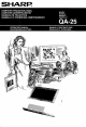
Thank you for purchasing this SHARP Product. We hope it will give you many years of trouble-free enjoyment. But for the best performance, read this Manual carefully. It will guide you in repeating your SHARP product. @ The Sharp Computer Projection Panel incorporates the latest development in Super Twisted High Contrast Liquid Crystal Display technology.
1.
2. UNPACKING Unpack and check that all of the components are in the carton. Please retain the Operation Manual for future reference.
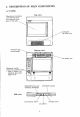
3. DESCRIPTION OF MAIN COMPONENTS (a) PANEL Monochrome trans missive Top view 1D (640200 dots} T with reinforced safety glass on both sides Cooling fan (air intake vent) o o Fahd-down type. carrying handle e Bottom view Air outflow vent. Adjustment controls (covered by protective door).
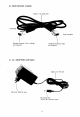
(b) RGB SIGNAL CABLE Approx. 2 m signal cable Personal computer CGA {or RGB) Computer Projection Panel end connector end connector (c) AC ADAPTER (ADP-0031) Approx. 2m DC cord 220 Volt, 50Hz AC plug \ DC output plug (5.5mm dia.
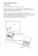
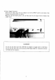
4. DIRECTIONS FOR USE (a) POSITIONING 1) Set your overhead projector in the best position for projection. 2) Place your personal computer in a convenient position next to the overhead projector. The approximately 2 m long DC cord of the AC Adapter and RGB Signal Cable allow flexible positioning to fit a variety of projection environments.
(b} CONNECTION Before performing any electrical connections, please make sure both the overhead projector and personal computer are turned off. 1) RGR Signal Cable Connection Taters the personal computer end connector of the RGB Signal Cable into the computer’'s CGA (or RGB) output socket. Securely fasten the connector to the socket with a screwdriver (see below).
2) Power Supply Connection Insert the DC output plug of the AC Adapter into the DC INPUT socket on the side of the Computer Projection Panel (sze below). Make sure that the Panel's power is off, and then insert the AC plug of the AC Adapter into a 220V outlet. CAUTION Do not use any other type of the ADP-0031 AC Adapter to supply power to the Panel. Do not use any other type of the accessory RGB Signal Cable for connection between the Panel and the computer.
OPERATION STEPS When you have connected the Computer Projection Panel to the personal computer, go on to Adjustment and Operation according to the following procedures. 1) Turn the Computer Projection Panel on. Caution: ® Do not turn the overhead projector power switch on when the Panel power switch is off. # The built-in cooling fan in the Panel body operates when the Panel’s power switch is on. This fan prevents temperature increases in the Panel.
B) The BACKGROUND switch gives you the option of reversing (inverting) the screen’s (white level black level) background color. When this switch is in “REVERSE” position, anything normally appearing “white” would be displayed “black”, and anything normally appearing “black” would be displaced “white™. Select the appropriate background for your images to be displayed. 6) When the image is not centered on the LCD, or characters and graphics flicker, signal control adjustment may he required.
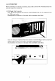
5. PROJECTION IMAGE ADJUSTMENTS {Located in computer interface adjustment compartment) (a) EXPLANATION OF ADJUSTMENT CONTROLS The following instructions explain how to adjust the position of the image, correct image flickering, and make RGB signal selections. These adjustments are made with the seven rotary DIP-switches and three On/OF switches located on the bottom of the Patel, beneath the protective door. V-PEWS H-PEWS FREQ.
NOTES 1. These controls are all factory preset for use with most versions of the IBRM-PC. Prior to initial use, readjustment of these controls may be required, depending on the specific computer and software package being used. Further slight readjustment of these controls may also be necessary, when going from one computer to another, from one mode to another, or from one software package to another. 2. A protective door prevents accidental maladjustment of these controls by non-technical users. 3.
Sapless BASIC program for adjustment procedure 10 FOR N=0 TO 1958 20 PRINT “f1™; 30 NEXT N 40 GOT 40 rin (Characters " will be fully displayed on the LCD.) Display where no adjustment is needed 1) Vertical Adjustment While looking at the LCD, use the upper rotary V-PEWS DIP-switch to make a coarse adjustment, bringing the display’s vertical position near to the center of the LCD. Then, use the lower V-PEWS adjustment DIP-switch to make fine centering adjustments.
{ 2) Horizontal Adjustment While looking at the LCD, use the upper rotary H-PEWS DIP-switch to make a coarse adjustment, bringing the display’s horizontal petition near to the center of the LCD. Then, use the lower H-PEWS adjustment DIP-switch to make fine centering adjustments. Horizontal adventurous needed e G 3) Frequency Adjustment, The two FREQ rotary DIP-switches adjust the Panel's frequency to match that of your computer.
“Technical” Adjustment of Frequency The frequency adjustment procedure described on page 15 will achieve very good results. However, for more “technical” users, the following much more detailed adjustment procedure will provide an even more exacting match of the Panel’s frequency to that of the computer. “The second digit of the Panel's frequency indicates a hexadecimal expression for COARSE ADJUSTMENT. "The first digit represents, in hexadecimal, an equivalent expression for FINE ADJUSTMENT.
5) RGB Signal Selection This display is capable of producing “monochrome” colors (dark bite images with a light gray background). Each of the color values being input into the Panel can either be set to appear as “white” (light gray), or “black” (dark blue) using the RGB input select switches located on the boom of the Panel under the protective door. [When the input select switch is “on”, that color will appear as “black™; when the input select switch is “off”, that color will appear as “white”.
The following is a list of all of the possible setting combinations for the RGB input select switches, and how each color will appear when projected using the Computer Projection Panel: Setting Combination The following colors appear as “black™ red, green, blue, brown, cyan, magenta, white # The following color appears as “white”: black Setting Combination OFF @ The following colors appear as “black™ red, green, brown, cyan, magenta, white ® The following colors appear as “white™: black, blue Setting Combin
Setting Combination OFF B: OFF @ The following colors appear as “black™ red, brown, magenta, white e The following colors appear as “white”: black, green, blue, cyan Setting Combination #6¥ R: OFF G: ON B: OFF ® The following colors appear as “black™ green, brown, cyan, white o The following colors appear as “white”: black, red, blue, magenta * Note: This is the original factory setting Setting Combination #7 R: OFF G: OFF B: ON ® The following colors appear as “black”: blue, cyan, magenta, white ® The foll
6. TRANSPORTING THE UNIT & Use the guilt-in carrying handle for short-distance carrying. Simply pull up the fold-down type carrying handle on the back of the hod and use it to carry the Panel. NOTE Handle the Panel with care; avoid rough handling such as swinging or bumping. The Computer Projection Panel has delicate internal mechanisms, as well as glass components. ¢ Cary the Pane!l carefully in a briefcase when transporting it over long distances.
7. MAINTENANCE ! The Computer Projection Panel has been designed to require very little maintenance. ® Check that the Power switch is OFF before performing any maintenance to the unit. 1. Cleaning the top and bottom glass surfaces, You may clean the glass surfaces of the Panel using a soft cloth moistened with any standard glass cleaner. 2. Cleaning the plastic cabinet. The cabinet may be cleaned using a soft cloth and a diluted soap solution.
8. TROUBLESHOOTING Before calling for service, please closely review the following troubleshooting information. Problems: 1. No picture appears on the Computer Projection Panel. 2. Picture image is “inverted” {black images appear as white; white images appear as black). 3. Display is off-centered or flickering, certain images do not appear on the display, or the display appears to be “broken up”. 4.
] Problems: 5. Projected images appear out of focus. Possible Solutions: Mike sure the overhead projector is a good quality trans missive type (and not a compact reflective mirror type). ® Make sure the overhead projector is in focus. Make sure the Panel is centered on the top of the overhead projector. The display may require an adjustment to make it compatible with your computer or software. Please refer topazes Image Adjustments”.
(b) MECHANICAL SPECIFICATIONS 1) Panel Dimension: 325 (W) x 365 Net Weight: 2.7kg (6 Abs) 2) LCD LCD Type: Super Twisted High Contrast Monochrome LCD Display Area: 208 (W) x 130 (H) mm Display Format: 80 characters X 25 lines 640 (W) x 200 (H) pixels Duty: 17100 Dot Size: 0.285 (W) x 0.61 (H) mm Dot Spacing: 0.
(d) CONTROLS AND CONNECTORS 1) Located on the side of the Panel BACKGROUND (NORMAL/REVERSE) Switch CONTRAST Control ’ RGB SIGNAL INPUT Terminal D-SUB) DC INPUT (5.5 mm: dia.
4) Input Signal Timing RGR signal Horizontal syn signal RGB signal Vertical syn signal Timing ratings Notes: Tck = lick (IBM-PC CGA: fck = 14.318 MHz) Thd = Tek X 640, Tvd = Th x 200 Parameter Symbol Mir. Max. Units Horizontal period Horizontal sync signal pulse width Hs tuck Th-tuck — Horizontal display start waiting time Ths 5Tk 256Tck et Vertical period Tv 16.
(f) INPUT TERMINALS 1) RGB SIGNAL INPUT connector (at the side of the Panel), The RGB separate video signal from a personal computer is input using the Signal Cable. W Pin assignment @O GND & GND @ R signal @ G signal & B signal Horizontal sync signal @ Vertical sync signal B Connector 9-pin D-SUB 23 DC INPUT connector Connect the AC Adapter plug to this connector. 5.5mm diameter concentric fig Inside: Positive Q Outside: GND (g) INCLUDED ACCESSORIES (1)RGB Signal Cable (Approx. 2 m) (Sharp Part No.