
Service manual
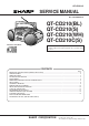

QT-CD210/C
– 3 –
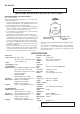
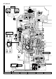
NAMES OF PARTS
11.
(TAPE) Record Button
12.
(TAPE) Play Button
13.
(TAPE) Rewind Button
14.
(TAPE) Fast Forward Button
15.
(TAPE) Stop/Eject Button
16.
(TAPE) Pause Button
17.
Cassette Compartment
18.
CD Compartment
19.
Tuning Control
10.
(CD) Stop Button
11.
(CD) Track Down/Review Button
12.
Volume Control
13.
Function Selector/Power Switch
14.
(CD) Track Up/Cue Button
15.
(CD) Play/Pause Button
16.
(CD) Play Indicator
17.
(CD) Pause Indicator
18.
Battery Compartment
19.
FM Telescopic Rod Aerial
20.
AC Power Input Socket
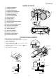
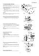
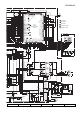
FITTING OF DIAL POINTER
Figure 3-2
Main
PWB
Main
PWB
Dial Pointer
Drum
Dial
Pointer
Dial Pointer
Top Cabinet
Tuning
Knob
Top Cabinet
Drum
A
Top Cabinet
Drum
Variable Capacitor
B
123
456
78
9
10
15
16
17
12
13 14
11
18 19 20
Setting method of the dial pointer
1. Remove the front cabinet. (Refer to Fig.4-1 on page 4,
"Disassembly method".)
2. Remove the dial pointer.
3. Insert the dial pointer from A of the top cabinet so that it
engages with the drum gear.
4. Fully turn the drum in the opposite direction of B and set
it to the FL marks.
5. Reassemble the front cabinet.
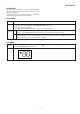
Figure 3-1
FL Mark
Carved Seal
Mark
FH
FL