Models C709/C717 Heat Treatment Soft Serve Freezers Original Operating Instructions 062080--M 2/4/05 (Original Publication) (Updated 5/14/12
Complete this page for quick reference when service is required: Taylor Distributor: Address: Phone: Fax: E-mail: Service: Parts: Date of Installation: Information found on the data label: Model Number: Serial Number: Electrical Specs: Voltage Cycle Phase Maximum Fuse Size: A Minimum Wire Ampacity: A EFebruary, 2005 Taylor All rights reserved. 062080-M The word Taylor and the Crown design are registered trademarks in the United States of America and certain other countries. Taylor Company 750 N.
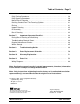
Table of Contents Section 1 To the Installer . . . . . . . . . . . . . . . . . . . . . . . . . . . . . . . . . . . . . . . . . . . . 1 Installer Safety . . . . . . . . . . . . . . . . . . . . . . . . . . . . . . . . . . . . . . . . . . . . . . . . . . . . . . . . Site Preparation . . . . . . . . . . . . . . . . . . . . . . . . . . . . . . . . . . . . . . . . . . . . . . . . . . . . . . . Air Cooled Units . . . . . . . . . . . . . . . . . . . . . . . . . . . . . . . . . . . . . . . . . . . . . . . . . . .
Table of Contents - Page 2 Daily Closing Procedures . . . . . . . . . . . . . . . . . . . . . . . . . . . . . . . . . . . . . . . . . . . . . . Daily Opening Procedures . . . . . . . . . . . . . . . . . . . . . . . . . . . . . . . . . . . . . . . . . . . . . . Manual Brush Cleaning . . . . . . . . . . . . . . . . . . . . . . . . . . . . . . . . . . . . . . . . . . . . . . . . Draining Product From The Freezing Cylinder . . . . . . . . . . . . . . . . . . . . . . . . . . . . Rinsing . . . . . . . . . . . .
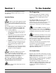
Section 1 To the Installer The following are general installation instructions. For complete installation details, please see the checkout card. Site Preparation Review the area where the unit will be installed before uncrating the unit. Make sure all possible hazards to the user or equipment have been addressed. Installer Safety For Indoor Use Only: This unit is designed to operate indoors, under normal ambient temperatures of 70_-75_F (21_-24_C).
inside of the electrical box for proper power connections. Water Connections (Water Cooled Units Only) An adequate cold water supply must be provided with a hand shut-off valve. On the underside of the base pan or on the right side, two 3/8” I.P.S. water connections for inlet and outlet are provided for easy hook-up. 1/2” inside diameter water lines should be connected to the machine. (Flexible lines are recommended, if local codes permit.
Beater Rotation Refrigerant liquid sprayed onto the skin may cause serious damage to tissue. Keep eyes and skin protected. If refrigerant burns should occur, flush immediately with cold water. If burns are severe, apply ice packs and contact a physician immediately. Beater rotation must be clockwise as viewed looking into the freezing cylinder. Note: The following procedures should be performed by a trained service technician.
Section 2 To the Operator Your freezer has been carefully engineered and manufactured to give you dependable operation. When properly operated and cared for, it will produce a consistent, quality product. Like all mechanical products, cleaning and maintenance will be required. A minimum amount of care and attention is necessary if the operating procedures outlined in this manual are followed closely.
Section 3 Safety We at Taylor Company are concerned about the safety of the operator when he or she comes in contact with the freezer and its parts. Taylor has gone to extreme efforts to design and manufacture built-in safety features to protect both you and the service technician. As an example, warning labels have been attached to the freezer to further point out safety precautions to the operator.
S S S This freezer must be placed on a level surface. Failure to comply may result in personal injury or equipment damage. DO NOT allow untrained personnel to operate this machine. DO NOT operate the freezer unless all service panels and access doors are restrained with screws. DO NOT remove any internal operating parts (example: freezer door, beater, scraper blades, etc.) unless all control switches are in the OFF position.
Section 4 Operator Parts Identification Model C709 Figure 1 ITEM DESCRIPTION PART NO. ITEM DESCRIPTION PART NO. 10 PANEL A-SIDE-RIGHT X57871 1 PANEL-SIDE-LEFT 056963-SP1 2 PAN-DRIP 11-5/8 LONG 027503 11 PANEL A.-FRONT-UPPER X59423 3 PIN-RETAINING-HOPPER CVR 043934 12 PANEL A.-FRONT-LOWER X58955 4 KIT A.-COVER-HOPPER X65368 13 STUD-NOSE CONE 055987 5 BLADE A.-AGITATOR X56591 14 SHELF-TRAY-DRIP 056076 6 TUBE A.
Model C709 Single Spout Door and Beater Assembly Figure 2 ITEM DESCRIPTION PART NO. ITEM 1 HANDLE A.-DRAW-WELDED X56246 9 2 O-RING-1/4 OD X .070W 50 015872 3 SCREW-ADJUSTMT-5/16-24 4 NUT-STUD BLACK 3.250” 5 DESCRIPTION PART NO. PIN-HANDLE-SS 055819 10 GASKET-DOOR HT 4”-DBL 048926 056332 11 BEARING-FRONT 050216 058765 12 BEATER A.-3.4 QT HELICORE X31761 NUT-STUD BLACK 2.563“ 058764 13 BLADE-SCRAPER-PLASTIC 035174 6 DOOR A.
Model C717 Figure 3 111129 Models C709 & C717 9 Operator Parts Identification
Model C717 Exploded View Parts Identification ITEM DESCRIPTION PART NO. ITEM DESCRIPTION PART NO. 1 COVER-HOPPER 053809-1 14 PANEL A.-FILTER-LOUVERED X59928 2 BLADE A.-AGITATOR X56591 15 CASTER-4” SWV 3/4-10 STEM 044106 3 ORIFICE 022465-100 16 SCREW-1/4-20 X 3/8 RHM-SS 011694 4 TUBE A.-FEED-SC-INNER-3/16 X32824-3 17 TUBE A.-FEED-OUTER-HT X34641 PANEL-CORNER-FRONT RIGHT 063087 5 6 O-RING-.643 OD X .
Model C717 Three Spout Door and Beater Assembly Figure 4 ITEM DESCRIPTION PART NO. 1 HANDLE A.-DRAW-WELDED X56421-1 2 O-RING-1/4 OD X .070W 50 3 SCREW-ADJUSTMENT-5/16-24 4 ITEM DESCRIPTION PART NO. 10 BEATER A.-3.4QT-HELICORE X31761 015872 11 BLADE-SCRAPER-PLASTIC 17 035174 056332 12 SHAFT-BEATER 032564 NUT-STUD BLACK 3.250 LONG 058765 13 SEAL-DRIVE SHAFT 032560 5 NUT-STUD BLACK 2.563 LONG 058764 14 VALVE A.-DRAW-L&R X59888 6 DOOR A.
Feed Tube Assembly Figure 5 ITEM DESCRIPTION PART NO. ITEM DESCRIPTION PART NO. 1 AIR ORIFICE 022465-100 3 O-RING - .291 ID x .080 W 018550 1a O-RING 016137 4 TUBE A.-FEED-OUTER-HT X34641 2 TUBE A.-FEED-SC-INNER (C709) X32824-2 5 O-RING- .643 OD x .077 W 018572 TUBE A.
Accessories Figure 6 ITEM DESCRIPTION PART NO. 1 PAIL-MIX 10 QT. 013163 2 TOOL-O-RING REMOVAL 048260-WHT 3 LUBRICANT-TAYLOR HI-PERF 048232 ITEM *4 **5 DESCRIPTION PART NO. SANITIZER KAY-5 25 PACKS SEE NOTE KIT A.-TUNE-UP (C709) X49463-58 KIT A.-TUNE-UP (C717) X49463-79 *Note: A sample container of sanitizer is sent with the unit. For reorders, order Kay-5 part no. 041082 (200 packs) or Stera Sheen part no. 055492 (100 2 oz. packs).
Brushes Figure 7 ITEM DESCRIPTION PART NO. ITEM DESCRIPTION PART NO.
Section 5 Important: To the Operator Figure 8 ITEM 1 2 3 4 5 6 7 8 9 10 11 DESCRIPTION POWER SWITCH LIQUID CRYSTAL DISPLAY KEYPADS MIX OUT INDICATOR STANDBY KEY MIX LOW INDICATOR SELECT KEY SERVICE MENU KEY BRUSH CLEAN COUNTER ARROW KEYS TOPPING HEATER KEY 050321 Models C709 & C717 15 Important: To the Operator
Power Switch Symbol Definitions When placed in the ON position, the power switch allows control panel operation. To better communicate in the International arena, symbols have replaced words on many of our operator switches, function, and fault indicators. Your Taylor equipment is designed with these International symbols. Fluorescent Display The fluorescent display is located on the front control panel. During normal operation the display is blank.
To resume normal operation, press the AUTO symbol . When the unit cycles off, the product in the freezing cylinder will be at serving viscosity. At this time, turn the inner feed tube so the pin fits into the groove of the outer feed tube. Install the air orifice. WARNING: Do not use metal objects to press the reset button. Failure to comply may result in severe personal injury or death. If the beater motor is turning properly, touch the Wash Symbol WASH symbol to cancel the cycle.
The SAFETY TIMEOUT screen will be displayed with the alarm on, for 60 seconds or until any control symbol is selected. Operating Screen Descriptions The fluorescent display located in the center of the control panel is normally blank during the daily operation of the machine. The display is activated when the SEL symbol or the Manager's Menu is selected. The display screen will also alert the operator of specific faults detected by the control.
When the temperature of the mix is above 130°F (54.4°C) the screen will display a message indicating that HOT PRODUCT is in the machine. International Models Only: Some International models will continuously display the temperature of each mix hopper when the power switch is in the ON position. (See Figure 16.) HOPPER 3.
Selecting the WASH symbol following screen. To restore the message that identified the reason for the hard lock, turn the power switch OFF for five seconds and then return the power switch to the ON position. The original message with the reason for the Hard Lock will be displayed. The FAULT DESCRIPTION can also be found in the Manager's Menu (See page 26.) will display the FREEZER LOCKED The FREEZER LOCKED message will remain on the display until the brush clean requirements are fulfilled.
When one of these messages appears, automatic freezer operation cannot take place until the freezer is disassembled and brush cleaned, or has completed a heat treatment cycle. Select the HEAT Following are the variable messages for soft lock failures that appear on the second line of the screen. POWER SWITCH OFF Power switch was in the OFF position. MIX OUT PRESENT There was a mix out condition present. AUTO OR STANDBY OFF The machine was not in the AUTO or STANDBY mode.
The FAULT DESCRIPTION can also be found in the Manager's Menu. Entering Access Code Note: A record of Heat Cycle Data and Lock Out History can be found in the Manager's Menu. (See page 27.) With the ACCESS CODE screen on the display use the SEL symbol to set the first code number in the cursor position. When the correct number is selected, touch the SEL symbol to move the cursor to the next number position. Manager's Menu The Manager's Menu is used to enter the operator function displays.
Reset the SERVING COUNTER by selecting the SEL symbol to advance to the next screen. Select the UP arrow symbol to move the arrow (>) to YES and select the SEL symbol. The servings counter will reset to zero and exit back to the Manager's Menu. Menu Options Touch the ARROW symbols to move up or down through the Menu. Select a Menu option by touching the SEL symbol. Exit the Menu program by selecting EXIT FROM MENU or touch the CONE symbol . The following menu options are listed in the Manager's Menu.
Change the time by touching the UP arrow with the cursor under the hour position. Move the cursor to the minutes by touching the SEL symbol. Once the correct minutes are entered, touch the SEL symbol to advance the cursor to the month. To set the AUTO HEAT TIME select the UP arrow symbol to move the arrow to Change. Then touch the SEL symbol. The screen will display the time with the cursor under the hour position.
Program the AUTO START TIME by selecting the UP arrow symbol to move the arrow to Change. Touch the SEL symbol to advance to the next screen. The following message will be displayed if the BRUSH CLEAN CYCLE option is selected when the machine is not in a brush clean state. BRUSH CLEAN CYCLE No Changes Allowed AUTO START TIME 00:00 Press Any Key Figure 44 Figure 42 Change the number of days between brush clean intervals by using the arrow symbols.
The second line of the screen displays the date and time a failure occurs. The third line indicates the reason for a failure, or will indicate if a successful brush cleaning has occurred. Some failures occur with multiple reasons. When this occurs, a page will be generated for each reason. The FAULT DESCRIPTION display will indicate if there is a fault with the freezer. When no faults are detected the following screen will be displayed.
HOPPER THERM FAIL - The thermistor sensor for the hopper failed. The first screen displays the month and day of the heat cycle, and the start time and end time the machine underwent the heat treatment cycle. The “B” on the right side indicates that both sides of the freezer are in operation. Line 3 displays the total time in each heat cycle phase. Line 4 displays the length of time of the last successful phase and the page number. Normally this time will be the COOL phase.
control and software version installed in the machine. Listed below are variable failure code messages which could appear on line 2. HT Heat Time Too Long Mix temperature did not rise above 151°F (66.1°C) in less than 90 minutes. CL Cool Time Too Long Mix temperature in the hopper and freezing cylinder did not fall below 41°F (5°C) in less than 120 minutes. TT SOFTWARE VERSION C709 CONTROL UVC3 VERSION 1.
Section 6 Operating Procedures The C709 machine stores mix in a hopper. It has a 3.4 quart (3.2 liter) capacity freezing cylinder with a single spout door. The C717 machine stores mix in two hoppers. It has two 3.4 quart (3.2 liter) capacity freezing cylinders with a three spout door. We begin our instructions at the point where we enter the store in the morning and find the parts disassembled and laid out to air dry from the previous night's cleaning.
Step 5 Slide the beater the remainder of the way into the freezing cylinder and over the end of the drive shaft. The beater should fit snugly, but not so tightly that the beater cannot be turned slightly to engage the drive shaft. If the beater slides in too easily with little or no resistance, there will not be enough force against the beater to hold the blades in place. Step 3 Take one of the scraper blades and slip it under the hook at the front of the beater.
Model C709 Freezer Door Assembly (Cont'd.) Step 2 Slide the three o-rings into the grooves on the draw valve and lubricate. (See Figure 62.) Figure 64 Step 5 Insert the baffle rod through the beater in the freezing cylinder. With the door seated on the freezer studs, install the handscrews, with the longer ones on top. Tighten equally in a criss-cross pattern to insure the door is snug. (See Figure 65.) Figure 62 Step 3 Lightly lubricate the inside of the top of the freezer door valve cavity.
Model C709 Freezer Door Assembly (Cont'd.) Model C717 Freezer Door Assembly Note: The C709 features an adjustable draw handle to provide portion control, giving a better consistent quality to your product and controlling costs. Step 1 Place the door gaskets into the grooves on the back of the freezer door. The draw handle should be adjusted to provide a flow rate of 5 to 7-1/2 oz. (142 g. to 213 g.) of product by weight per 10 seconds. To INCREASE the flow rate, turn the adjustment screw CLOCKWISE.
Step 3 Insert the baffle rods through the beaters in the freezing cylinders. With the door seated on the freezer studs, install the handscrews, with the longer ones on top. Tighten equally in a criss-cross pattern to insure the door is snug. Step 5 Lubricate the inside of the freezer door spouts, top and bottom. Figure 73 Step 6 Insert the draw valves from the bottom until the slot in each draw valve comes into view. Figure 71 Step 4 Slide the three o-rings into the grooves of each standard draw valve.
Model C717 Freezer Door Assembly (Cont'd.) Step 8 Slide the pivot pin through the draw handles as the handles are inserted into the draw valves. Step 11 Install the front drip tray and splash shield under the door spouts. (See Figure 77.) Figure 75 Note: This freezer features adjustable draw handles to provide portion control, giving a better consistent quality to your product and controlling costs. The draw handles should be adjusted to provide a flow rate of 5 to 7-1/2 oz. (142 g. to 213 g.
Step 2 Slide the two o-rings into the grooves of the outer feed tube. Step 4 Lay the inner feed tube, the outer feed tube, and the agitator in the bottom of the mix hopper for sanitizing. Figure 81 Repeat Steps 1 through 4 for the other side of the C717. Figure 79 Sanitizing Step 1 Prepare an approved 100 PPM sanitizing solution (examples: 2--1/2 gal. [9.5 liters] of Kay--5R or 2 gal. [7.6 liters] of Stera--SheenR). USE WARM WATER AND FOLLOW THE MANUFACTURER’S SPECIFICATIONS.
Step 3 While the solution is flowing into the freezing cylinder, take particular care to brush-clean the mix level sensing probe on the bottom of the hopper, the mix hopper, the mix inlet hole, and the feed tubes. Step 8 Lubricate the o-rings on the inner and outer feed tubes. DO NOT lubricate the o-ring on the air orifice. Place the inner feed tube inside the outer feed tube. Step 4 Place the power switch in the ON position.
Step 10 Stand the assembled feed tube in the corner of the mix hopper and place the agitator on the agitator housing. Figure 87 Figure 86 The pin on the inner feed tube should be turned and positioned at the bottom of the notch in the outer feed tube. This will align the holes in the feed tubes and allow mix and air to enter the freezing cylinder. Step 11 Return to the freezer with a small amount of sanitizing solution.
Step 4 Prepare a small amount of an approved 100 PPM cleaning/sanitizing solution (examples: Kay-5® or Stera-Sheen®). USE WARM WATER AND FOLLOW THE MANUFACTURER'S SPECIFICATIONS. Brush clean the parts. Daily Closing Procedures This procedure must be performed once daily! Step 5 Place the front drip tray, splash shield, and air orifice(s) on a clean, dry surface to air-dry overnight or until the heating cycle is complete.
Step 9 Replace the hopper cover(s) and install the drip pans. A failure message will appear on the fluorescent display to inform the operator that the machine did not successfully complete the heat treatment cycle. The product may not be safe to serve. The freezer will be locked out (softlock) of the AUTO mode. The operator will be given the option of selecting the Step 10 Return to the freezer with a small amount of cleaning solution.
Step 6 Lift the hopper cover(s). Turn the inner feed tube of each assembled feed tube so the pin rests at the bottom of the notch of the outer feed tube. Install the air orifice(s). Step 3 Return to the freezer with a small amount of sanitizing solution. Dip the door spout brush into the sanitizing solution and brush clean the door spout(s) and bottom of the draw valve(s).
Draining Product From The Freezing Cylinder Rinsing Step 1 Pour two gallons (7.6 liters) of cool, clean water into the mix hopper. With the white hopper brush, scrub the mix hopper, mix level sensing probes and the outside of the agitator drive shaft housing. Using the double ended brush, brush clean the mix inlet hole. Step 1 Press the AUTO symbol , cancelling compressor and beater motor operation. Step 2 Remove the hopper cover, the agitator paddle, and the assembled feed tube.
Step 3 Open the draw valve on the freezer door. Drain all the rinse water from the door spout, close the draw valve and touch the WASH symbol, wash mode. Disassembly Note: Failure to remove the parts specified below for brush cleaning and lubrication will result in damage to the machine. These parts must be removed every 14 days or the machine will lock out and will not operate. cancelling the Step 4 Repeat this procedure using clean, warm water, until the water being discharged is clear.
Step 5 Return to the freezer with a small amount of cleaning solution. Using the black brush, clean the rear shell bearing at the back of the freezing cylinder. Brush Cleaning Step 1 Prepare an approved 100 PPM cleaning solution (examples: 2-1/2 gal. [9.5 liters] of Kay-5R or 2 gal. [7.6 liters] of Stera-SheenR). USE WARM WATER AND FOLLOW THE MANUFACTURER'S SPECIFICATIONS. Make sure all brushes provided with the freezer are available for brush cleaning. Step 2 Remove all o-rings.
Section 7 Important: Operator Checklist During Brush Cleaning and Sanitizing Regular Maintenance Checks j 1. Replace scraper blades that are nicked or damaged. Before installing the beater assembly, be certain that scraper blades are properly attached to the helix. ALWAYS FOLLOW LOCAL HEALTH CODES. Cleaning and sanitizing schedules are governed by your State or local regulatory agencies and must be followed accordingly.
j 7. If your machine is equipped with an auxiliary refrigeration system, check the auxiliary condenser for accumulation of dirt and lint. Dirty condensers will reduce the refrigeration capacity of the mix hopper. Condensers must be cleaned monthly with a soft brush. Never use screwdrivers or other metal probes to clean between the fins.
Section 8 PROBLEM 1. Soft lock message appears on display. 2. Hard lock message appears on display. Troubleshooting Guide PROBABLE CAUSE REMEDY PAGE REF. a. An equipment fault has occurred. a. Determine reason the failure occurred. Correct cause for failure, then select HEAT symbol to start a heat cycle or WASH to disassemble and brush clean the machine. 20 b. More than 24 hours since the last HEAT cycle. b. The freezer must go through a HEAT cycle every 24 hours.
PROBLEM 3. No product is being dispensed. 4. The product is too soft. Models C709 & C717 PROBABLE CAUSE REMEDY PAGE REF. a. Low on mix. The MIX OUT light is on. a. Add mix to the mix hopper. Return to AUTO mode. 37 b. The power switch is in the OFF position. b. Place the power switch to ON and select AUTO. 36 c. The circuit breaker is off or the fuse is blown. c. Turn the breaker on, or replace the fuse. -- -- -- d. Beater motor is out on reset, BEATER OVERLOAD message displayed. d.
PROBLEM REMEDY PAGE REF. a. Freezing cylinder not primed correctly. a. Drain the freezing cylinder and reprime the machine. 37 b. The viscosity control is set too cold. b. Call an authorized service technician. --- c. Freeze-up in mix inlet hole. c. Call an authorized service technician. --- a. Hopper cover is not in position. a. Clean and sanitize hopper cover and place in position. 37 b. The agitator is not installed. b. Clean and sanitize the agitator and install. 38 c.
PROBLEM PROBABLE CAUSE 12. The drive shaft is stuck in the drive coupling. a. Mix and lubricant collected in drive coupling. a. Brush clean the rear shell bearing area regularly. 43 b. Rounded corners of drive shaft, drive coupling, or both. b. Call an authorized service technician. --- c. Gear box is out of alignment. c. Call an authorized service technician. --- a. Missing or worn front bearing and scraper blades. a. Install or replace the front bearing and scraper blades. 30 b.
Section 9 PART DESCRIPTION Parts Replacement Schedule EVERY 3 MONTHS EVERY 6 MONTHS ANNUALLY White Bristle Brush, 3” x 7” Inspect & Replace if Necessary Minimum White Bristle Brush, 1” x 2” Inspect & Replace if Necessary Minimum Black Bristle Brush, 1” x 2” Inspect & Replace if Necessary Minimum Double-Ended Brush Inspect & Replace if Necessary Minimum Yellow Bristle Brush Inspect & Replace if Necessary Minimum Scraper Blades X Drive Shaft Seal X Freezer Door Gasket X Front Bearing
Section 10 Warranty Explanation Class 103 Parts Class 512 Parts The warranty for new equipment Class 512 parts is five years from the original date of unit installation, with a replacement parts warranty of twelve months. The warranty for new equipment Class 103 parts is one year from the original date of unit installation, with a replacement parts warranty of three months. Class 000 Parts Class 000 parts are considered wear items - no warranty.
Parts List 52 028992 028991 012864 +WASHER-BEARING LOCK 031324 BEARING-REAR SHELL-NICKEL +GUIDE-DRIP SEAL +NUT-BRASS BEARING 050216 BEARING-FRONT 045141 028889 SCREW-4-40X1" TAPTITE PAN HD SWITCH-LEVER-SPDT-10A-125 038924 X69838 SPRING-RETURN-RIGHT-TWIN TWIST +SWITCH A.-DUAL LEVER 069839 038923 SPRING-RETURN-LEFT-TWIN TWIST 062408 067352 SPRING-EXTENSION.500X.054X1.
+ Available Separately Models C709 & C717 53 Parts List 040040-013 040040-042 CABLE-RIBBON-20C-17"L-DIL/DIL CABLE-RIBBON-20C-18"L-DIL/DILR 040040-058 056864 040040-040 CABLE-RIBBON-14C-3"L-SIL/SIL CABLE-RIBBON-20C-14"L-DIL/DIL CABLE-RIBBON-50C-10"L-DIL/DIL 040040-015 CABLE-RIBBON-14C-14"L SIP/SIP 040040-049 040040-010 040040-025 CABLE-RIBBON-50C-25"L.
+ Available Separately Parts List 54 Models C709 & C717 048259-27E 033044-1 COMPRESSOR L64A113BBCA +CAPACITOR-START 189-227UF/33 055813-2 X69354-SER X68114-SER CONDENSER-AC 12LX18HX3.12T-5RW PCB A.
+ Available Separately Models C709 & C717 55 Parts List X56421-1 015872 +HANDLE A.-DRAW *C602* +O-RING-1/4 OD X .070W 030788 052779-9 FASTENER-DOOR STRIKE FILTER-AIR-21.688X15.813HX.70W 056934 013739 030787 EYELET-RESET BUTTON FASTENER-DOOR LATCH GASKET-BASE PAN 066247-DVD DVD-OPS TRAIN VIDEO *C709* 052779-11 040140-001 049154 DRYER-FILTER 3/8 X 3/8SOL HP FILTER-AIR-POLY-FLO FILTER-CORCOM 6EH1 034698 048901 +SEAL-DRAW VALVE DRYER-FILTER-HP62-3/8 X 1/4S X59890 +VALVE A.
+ Available Separately Parts List 56 Models C709 & C717 057723-SP 057728 068351 062050 066440-27G 067822 HARNESS-WIRE-MX PRB-CONT SW HARNESS-WIRE-THERMISTOR PROBES HARNESS-WIRE-SOL VLV/FAN MTR HARNESS-WIRE-LW V-MIX HOPPER HARNESS-WIRE-BEATER MTR HARNESS-WIRE-LW V-CNTRL 050216 045191 X49463-92 LABEL-CAUTION-AGITATOR KIT A.-TUNE UP *1SPOUT* *C709* BEARING-FRONT X67061 KIT A.-COVER-HOPPER*DUAL*BLK 600165 SCREW-4-40X1/4 SOC SS 045191 017395 O-RING-1-3/8 OD X .
+ Available Separately Models C709 & C717 57 Parts List 016137 018550 018572 032560 048260-WHT O-RING-3/8 OD X .070W O-RING-.291 ID X .080W O-RING-.643 OD X .077W SEAL-DRIVE SHAFT TOOL-O-RING REMOVAL-FREEZER 032717 051433 057870 036435 048232 062080-M LABEL-WARN-ELEC-SGL-SMALL LABEL-WARN-COVER LIP-DRIP LIP-DRIP-NOSE CONE LUBRICANT-TAYLOR HI PERF-4 OZ MAN-OPER C709/C717 021522-33 032749 052632 LABEL-DOOR-MOVE PART LABEL-SW-POWER-OFF/ON-SYMBOLS MOTOR-1.
+ Available Separately Parts List 58 Models C709 & C717 X40828-SER X58505-SER X46904-SER PCB A.-PERSONALITY-HT-SS 062529-SER CHIP-SOFTWARE C708 UVC3SM PCB A.-INTERFACE-HT-SS-UK CONTROL-UVC3 SURFACE MNT-PWM X59209-SER PCB A.-CONTROL *C708* UVC3SM X68114-SER CONTROL-UVC4 X40625 X69354SER1 X69354-SER PCB A.-CONTROL UVC4 +MODULE-PROGRAM C708/C709 UVC4 PCB A.-CONTROL *C708* UVC4 CONV KIT 059907 059917 PANEL-SIDE-RIGHT *C712/C717* PANEL-REAR *C713/C717* X57871 056963-SP1 PANEL A.
+ Available Separately Models C709 & C717 59 Parts List 062124 029595 X56912 056908 PLATE-DEC *C717* SYRUP RAIL PLUG-DRIP TRAY HOLE PROBE A.-MIX PROBE-MIX OUT *C708* 052111-03 027822 PULLEY-2AK74-5/8 RELAY-DPDT 100UA TO 7A 1/8HP 016403 PULLEY-2AK22 X .625-.
+ Available Separately Parts List 60 Models C709 & C717 062299 X56147 X56253 STRAINER-CONE MESH 1/2 ODF SWITCH A.-DRAW ARM A.-DRAW 041660 041661 028889 SPRING-RETURN-LEFT-SELF CLOSE SPRING-RETURN-RIGHT-SELF CLOSE SWITCH-LEVER-SPDT-10A-125-250V X69838 028890 SCREW-4-40X1 RD HD STEEL-ZP SWITCH A.-DUAL LEVER *C71 038623 015478 NUT-4-40 HEX -PLATEDPIN-PIVOT 029099 062298 STRAINER-CONE MESH-1/4 ODF 049178 066794-33H 066794-33G STARTER-3 PHASE 2.5 TO 4 AMP STARTER-3 PHASE 1.6 TO 2.
+ Available Separately Models C709 & C717 61 Parts List 028889 SWITCH-LEVER-SPDT-10A-125-25 056965 059896 059897 X32824-2 018550 X34641 TRIM-CORNER-REAR-RIGHT *C708* TRIM-CORNER-REAR-L TRIM-CORNER-REAR-R TUBE A.-FEED-SC-INNER-5/3 +O-RING-.291 ID X .080W TUBE A.-FEED-OUTER-HT 018550 053565 046365 VALVE-EXP-AUTO-1/4S X1/4 FPT X32824-3 +O-RING-.291 ID X .080W VALVE-ACCESS-1/4MFL X 3/8OD SOLDER TUBE A.-FEED-SC-INNER-5/3 018572 056964 TRIM-CORNER-REAR-LEFT *C708* +O-RING-.643 OD X .
+ Available Separately Parts List 62 Models C709 & C717 053511-27 048626-27 043449-27C 043449-27 VALVE-SOL 1/8ORF 1/4 IN X 3/8 OUT VALVE-SOLENOID 7/16 ORF 5/8 ODF COIL-SOLENOID VALVE ARMS VALVE-SOLENOID 7/64ORF X 1/4S 059929 016289 022505 R50200 X59307-27 DEFLECTOR-BLOWER-EXHAUST FAN-5 BLADE 7 " PUSH 30 DEG CW GUARD-BLOWER HOSE-RUBBER 1/2 ID X 7/8 OD MOTOR A.-FAN WC X25900 058932 062160 062161 062043 X58935 048231 032953 OUTLET A.-TEE PANEL-SIDE-RIGHT-WC PANEL-SIDE-L. W/C PANEL-SIDE-R.
+ Available Separately Models C709 & C717 63 Parts List 048259-33 048259-40 023739 COMPRESSOR L63A113DBLA COMPRESSOR L63A113BBKA +CAPACITOR-RUN 25UF/370VAC +RELAY-START-COMPRESSOR 057010-39 057010-40 057010-58 059901-35 059901-40 059901-58 065436-58 06543640SP 057725-33G 066440-33G 058864-G 059245-G DIAGRAM-WIRING *C708/C709 DIAGRAM-WIRING *C708/C709 DIAGRAM-WIRING *C717* DIAGRAM-WIRING *C717* DIAGRAM-WIRING *C717* HARNESS-WIRE HARNESS-WIRE HARNESS-WIRE-BEATER MOTOR HARNESS-WIRE-BEATER MTR HA
+ Available Separately Parts List 64 Models C709 & C717 058285-58 068351-G 066107-G 020090 025949 021522-33 021522-34 056865-34 021522-35 X63966-SER HARNESS-WIRE-MAIN POWER HARNESS-WIRE-SOL VLV/FAN HARNESS-WIRE-SOLENOID LABEL-CK MOTOR ROTATE LABEL-3PH MOTOR PROT/1PH MOTOR-1.5 HP MOTOR-1.5 HP CAPS@10&2 O'CLOCK MOTOR-1.5 HP CAPS@8&10 O'CLOCK MOTOR-1.5 HP PCB A.-INTERFACE-HT-SS-UK ROHS 011545 066794-33H 066794-33J 032967 PULLEY-2AK27 X .625-.6265 STARTER-3 PHASE 2.
+ Available Separately Models C709 & C717 65 Parts List X59423-SP1 X62383-27 C20100-000 C20100-AFA X48464 X41141 X59229-1 X59229-2 X57847 X62568 X48014-12H X48014-27H X59454 X58699-27 X48014-12 X48014-27 036397 X62282 X62383-27 059234 CART FOR *C706/C707/C708/ CART FOR *C706/C707/C708/ KIT A.-CONE DISPENSER-2/D KIT A.-CONE DISPENSER-4 T KIT A.-DECAL-FLAVORBURST KIT A.-DECAL-VANILLA C708 KIT A.-HOPPER LOCK SINGLE KIT A.-LOCK-DRAW VALVE-SINGLE KIT A.-SYR RAIL-SD MT-DUAL KIT A.
Model C709 057010-27 4/12
Model C709 057010-33 4/12
Model C709 057010-40 4/12
Model C709 057010-58 4/12
Model C717 059901-27 4/12
Model C717 059901-33 4/12
Model C717 059901-40 4/12
Model C717 059901-58 4/12