ECG for T5 fluorescent lamps Technical Guideline Electronic Control Gear to operate T5/Ø 16 mm fluorescent lamps ECG to operate T5-fluorescent lamps Features Product Overview Technical Details Instruction Manual Tender Documents FAQ May 2005
Contents 1. Introduction.......................................................................................... 6 1.1 History..................................................................................... 6 1.2 T5/∅ 16 mm-Fluorescent Lamps............................................ 7 1.2.1 High Efficiency FH®…HE........................................................ 8 1.2.2 High Output FQ®…HO............................................................ 8 1.2.3 Fluorescent Circular FC® ............
2.15 2.16 2.17 2.18 2.19 2.20 End of Life (EoL acc. to T.2) ................................................ 22 U-OUT .................................................................................. 22 Approval Marks..................................................................... 23 2.17.1 ENEC-Approval Mark ........................................................... 23 2.17.1.1 Safety acc. to EN 61347 ............................................ 23 2.17.1.2 Performance acc. to EN 60929 ...........
3.10 3.11 3.12 3.13 3.14 3.15 3.16 3.17 3.9.2.1 Measuring Point Temperature tc................................ 42 3.9.2.2 Ambient Temperature ECG : ta.................................. 43 3.9.3 Lamp Temperature ............................................................... 43 3.9.3.1 Maximum Luminous Flux for T5/∅ 16 mm-Fluorescent Lamps ........................................................................ 43 3.9.4 General Recommendations for Installation........................... 44 3.9.
.7 5.6.5 Dimensions ........................................................................... 60 FAQ ...................................................................................... 60 6. Special Applications ......................................................................... 61 6.1 Outdoor Application .............................................................. 61 6.1.1 Installation Instructions ......................................................... 61 6.1.2 OUTKIT....................
7.5.3 Luminaire Optimisation ......................................................... 76 7.5.4 Maximum luminous flux for FH…HE fluorescent lamps ....... 76 7.5.5 Verticalness Operation ......................................................... 76 8. Troubleshooting Tips ........................................................................ 77 8.1 General ................................................................................. 77 8.2 Equipment Behaviour on Overvoltage .............................
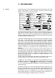
1. Introduction 1.1 History The development of linear fluorescent goes back to the thirties of the 20th century. The diameter of 51mm was very voluminous. However, better efficiency did not come up before the fifties. 1879 1968 Kohlefaden-Glühlampe von Thomas A. Edison Incandescent lamps with carbon filament by Thomas A.
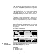
In 1996, the T5 lamp family was completed with the types of higher lumens than volume FQ®…HO (High Output)-fluorescent lamps. They are available in the wattage of 24, 39, 49, 54 and 80 W with the identical lengths as the FH…HE types. With up to 7000 lm for FQ 80 W HO this is the lamp family with the highest light output. In 1999, the third member of the T5/∅ 16 mm-lamp family was introduced to the market.
Consecutively the important data of the FH…HE, FQ…HO and FC fluorescent lamps are shown. 1.2.1 High Efficiency FH®…HE 1.2.2 High Output FQ®…HO 1.2.
ballast is responsible for preheating the lamp electrodes, for sufficient ignition voltage and for limiting the lamp current. 1.4 Different Principles, Different Behavior The basic functions that are mentioned in chapter 1.3, can usually be carried out with electromagnetic (inductive) ballasts. These ballasts are classified into conventional control gear (CCG) and low loss ballasts (LLG). The latter follow the same principle as CCG, however, due to different engineering design they consume less energy.
life. Electronic Control Gear improve the efficiency and the lamp life of fluorescent lamps significantly. 1.7 Ignition of Fluorescent Lamps Prior to ignition, modern ECG heat the cathode to its optimum temperature for electron emission. After a defined period the lamp is ignited with the required ignition voltage. Only an optimized preheat start can guarantee that the number of switching cycles has only little effect on the lamp life.
Burning hours per day 24 QUICKTRONIC® DIMMABLE QUICKTRONIC® PROFESSIONAL 20 Industry, Open space office 16 Department store, display 8 4 0 1.
2. Product Features 2.1 Lighting Comfort • • • • • No flashing or flickering, electronic defective control for reliable safety switch-off of defective lamps End-of-life safety shut down • Cut-off of the permanent filament preheating after lamp ignition Automatic restart after lamp replacement • 2.
In detail: • • • • • 2.4 2.4.
load distribution) unstable power supply (for example some countries in Far East) 2.4.2 Possible Implications due to Overvoltage 2.4.3 Undervoltage and its Reason It is called overvoltage, if the supply voltage exceeds the specified voltage range of an ECG including tolerances. In any case, overload means more stress to electronic components. Depending on the magnitude of overvoltage the protective functions of an ECG can come into effect and turn the ballast off.
2.4.6 Supply Voltage for QT with 30 mm height Valid for: QT-FH MULTIWATT and QT-FQ Recommended voltage range for continuous operation AC voltage 198V ... 264V, 50/60 Hz DC voltage 176V ... 264V Performance at undervoltage Lamp ignition UN ≥ 198V Î reliable lamp start UN ≥ 176V Î operation possible UN < 176V Î damage to ECG possible Voltage drop during operation 2.4.7 ECG for 120V / 277V Line Voltage T5/∅ 16 mm fluorescent lamps are also getting more popular in North America (USA, Canada).
Replace both lamps, take out the lamp replaced first and refit it. Provided lamp and ECG are o.k. both lamps should then light. 2.5.1 2.5.2 2.5.3 2.6 Lamp ignition for QTi Lamp ignition for QT to operate T5fluorescent lamps Off- Time for Optimum Preheat Start Behaviour in Response to Lamp Defects Lamp start Preheat Ignition time < 1 second Max. number of switching cycles > 100,000 cycles QT-FH MULTI, QT-FQ, QT…F/CW Lamp start Preheat Ignition time < 0.5 second Max.
• • Parallel circuit of lamps operated with multi-lamp ECG ≠in general single-lamp operation possible Parallel circuit of lamps, but no single-lamp operation possible because for example - the sum of electrodes has to be recognized For twin- and multi-lamp ECG the question is whether the remaining lamps will continue to operate if one lamp is defect or has been removed.
2.8 Power Factor λ For all electric loads, the power factor λ is the ratio of effective power (Peff = voltage x effective current) to apparent power (Papp = voltage x apparent current).
2.9 ECG Imprint Thermal Behaviour Functional Earth terminal Cut-Off-Technology µProzessor inside End-of-Life Safety-shutdown Lamp wiring including max. cable lengths 2.10 Reliability Besides component specification and quality their failure rate is significantly related to the operating temperature.
ECG provided by the manufacturer under consideration of the thermal load of electronic components. Surviving ECGs [%] 10 % loss at 50,000 hours 100 80 60°C 70°C 50°C 60 10°C lower operating temperature at point of measurement virtually halves ECG failure rate 90°C 40 Temp. at point of measurement tc 20 0 0 20 40 60 80 100 120 140 Hours of usage [thsd] 2.
2.14.1 Advantages for Users The following advantages for users arise from cut-off technology: 6-10 % higher luminaire efficiency highest lamp life 2-3 W lower losses per lamp reduced load of air condition Only cut-off technology can fulfill lifetime New circuitry wihtout permanent filament heating (cut-off technology) 100% IStift = ILampe Cold Spot app. 40°C 90% 13. 80% ILampe Rel.
system. The cut-off of the permanent filament heating after lamp ignition is an advantage. Further the values of the horseshoe curves also indicate the arrangement of the lamps within the fixture. To avoid thermal influences of the lamps minimum distances in between have to be kept. The lamps have to be placed that the stamp of all lamps is on the same side. For vertical arrangement the stamp of the lamp always should be placed down. For circular lamps FC the socket has to be placed down.
material and everything coming in contact with the ECG lamp terminals must be layed out according to U-OUT. OSRAM, as manufacturer, takes care that no higher voltage appears at the lamp terminals than specified by U-OUT. Therefore no additional voltage reserve is needed. 2.17 Approval Marks 2.17.1 ENEC-Approval Mark stands for European Norm Electrical Certification. The ENEC approval is also a conformity mark agreed upon between the testing institutes of the European union.
2.18 Energie Efficiency Index EEI This label helps consumers identifying the energy consumption of a product. Usually, all Electronic control gear have the best ratings A2 …A3. Dimmable ECG are classified as A1. Magnetic ballasts (CCG) fall under the energy efficiency class C and D and are either already banned from the market or are about to be banned shortly. Low loss ballasts are usually classified in B. 2.
does not make any statement with regards to the quality of labeled products. As a legal administration label without value for endusers it should not be mistaken as an approval mark issued by independent testing institutes (such as ENEC or VDE mark). These testing institutes do also not control the legitimacy of an applied CE label. 2.20 CCC Approval Approval mark of the Chinese testing institute CQC (China Qualification Center). Since 01.08.
3. ECG installed in Luminaire: Installations and Operation Instructions 3.1 Wiring Instructions 3.1.1 Cable Types 3.1.2 Cable Cross-Sections Please pay attention to the voltage value U-OUT imprinted on the ECG housing when wiring luminaires for FH®…HE or FQ®…HO fluorescent lamps. This value indicates the possible cable type. For voltages greater than 430V cables with the classification H07 have to be used.
3.1.2.1 ECG in 30 mm height Typical values for Combi-Wiring terminals of ECG with 30 mm height are: a) Single-core cables These should have a cross section of 0.5mm² at least and 1.5 mm² at most for the horizontal plug. When using Insulation Displacement Contacts (IDC) cables should have a maximum cross section of 0,5 mm² b) Multi-core cables horizontal plug These should have a cross section of 0,5 mm² at least and 1 mm² at most.
3.1.3.3 WAGO 251 – horizontal plug WAGO 251 – horizontal plug The contact can be released with the help of a small screw driver as Alternatively the contact can be released by simultaneously twisting and pulling the cable. 3.1.3.4 WAGO 251 mini – IDC Release the contact by pulling the cable upwards. This process can be repeated up to 10 times (depending on the manufacturer) without damaging the terminal. For further details please refer to the data sheets of the manufacturers.. 3.1.3.
3.1.4 Insulation Depending on the type of terminal the length of insulation to be stripped from the ends of the cables is different. The exact value can be found on the ECG. WAGO 250 Stripped Insulation [mm] 3.1.5 8-10 Terminals QT-FQ…CW QT-FH MULTI…CW QT-FH…F/CW QT-FQ…F/CW QT-FQ 2x80 QTi 3.1.6 Cable routing h = 30 mm WAGO 251 WAGO 251 WAGO 251 WAGO 251-mini 8.5 - 11 8.
Wiring must comply with the latest versions of the relevant national standards. Cable entry through metal components should never be left unprotected but should be fitted with additional insulation (sleeve, grommet edge protector etc.
Harmonic number 2 3 5 7 9 11 < n < 39 Proportion in % of the mains current of the fundamental wave (50 Hz) 2 30 x power factor(λ) 10 7 5 3 The specified values apply to Class C ECGs. OSRAM QUICKTRONIC® control gear typically exhibit values well below the threshold values. All QUICKTRONIC® units for operation of T5 FH®...HE- and T5 FQ®...HO fluorescent lamps have a total harmonic distortion (THD) of less than 10%. 3.2.
By using complex input filters it is possible to reduce these disturbances to a level well below the limits prescribed by the relevant standards. Each and every OSRAM ECG complies with these standards. The way in which an ECG is installed in a luminaire, however, can have a considerable influence. (see Section 7.5 Installation instruction for luminaires) 3.2.2.3 Disturbances due to Fields 3.2.2.
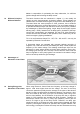
a) without reflector b) with a metal reflector The resulting magnetic field strength in the near field and hence the effect on the environment is reduced in b) by a current induced in a reflector. It is important here for the surface of the reflector to have good electrical conductivity. It is not necessary to earth it.
electromagnetic field. Serious problems can occur if, as described in Section xx, wiring instructions, the lamp cables that have high potential with respect to earth (hot wires) are not kept as short as possible by connecting them to the nearest lampholder. Lamp Hot wires The following diagrams apply to both recessed and surface-mounted luminaires: 3.2.2.6 Asymmetric installation of ECG Hot wires Cables should be laid close to the body of the luminaire. ECG and reflector need a low resistance earth.
Bad example The electrical connection between the ECG and the luminaire is poor. Unnecessary crossovers have been created leading to poorer and therefore higher resistance connection with earth. This arrangement is also poor from a thermal point of view. Übergänge Hot wires 3.2.2.7 Good wiring arrangement for 2lamp luminaires Hot wires 3.2.2.8 Luminaires with reflector and/or specular louvres These parts must be made of metal or at least have a surface (i.e.
b) Louvre instead of a reflector The same applies to louvers as to reflectors. Louvres also have to be good electrical conductors and be connected to luminaire earth. 3.3 Permissible Cable Lengths Section 7.1 refers to the maximum recommended cable lengths between the ECG and the lamp. The additional information is discussed elsewhere in this section.
„Hot wires“ are marked on the unit with the shorter cable length. For reasons of radio interference suppression and reliable starting, the “hot wires” must be kept as short as possible. In other words, you should install the ECG to one side in the luminaire, making the low-potential cables longer so that the length of the high-potential cables can be reduced. This type of installation is to be preferred to symmetrical mounting.
“master luminaire” and between the ECG and the lamp in the “slave luminaire”. The following requirements apply to the physical arrangement of the two luminaires: 3.6.1 Max. length of the connecting cable between 2 luminaries QTi 2x QT-FH 2x14-35/230-240 CW QT-FQ 2x…CW QT-FH 2x…/230-240 F/CW and QT-FQ 2x…/230-240 F/CW Max. length of the connecting cable between two luminaries [m] No master-slave circuit possible 1m 0.
UN 1 21 2 22 3 4 23 QTi 2x... 24 5 25 DA (–) 6 26 DA (+) 7 27 L L Wiring 2-lamp QTi To obtain good radio interference suppression, the PE conductor and the line mains cables should not be lais parallel to the lamp cables or alongside the ECG.
3.8.1 General Information The functional earth in this arrangement restores the internal short circuit of the system. Î no interaction of the capacitive currents of the system lampECG with the mains side and therefore no disturbances with regards to CISPR 15 measurements. Radio interference: 9 kHz to 300 MHz LN Low R Lamp ECG Plastics housing Due to the partly high lamp voltages of T5 fluorescent lamps we recommend to apply a functional earth to T5-lamps for improved radio interference suppression.
functional earthing! 2.) Instruction manual The necessity of the functional earthing of an ECG due to EMI reasons is noted in the technical data or in addition on the type label of the ECG with the appropriate symbol. The regulations for the skinning and the max. length of the wire are valid for L- and N-conductor. The length of the functional earth must not exceed the max. length of the other wires. IEC 60363/VDE V0800-2-548 have to be observed for the functional earthing. 3.) 3.
of T5/∅ 16 mm- fluorescent lamps FH®...HE and FQ®...FO have a very low thermal output, producing typically between 10 °C and 20 °C temperature rise. It allows a wide range of ambient temperatures which is covering almost all applications. If not, adequate measures must be taken in the luminaire or at the site of installation to improve the thermal balance of the luminaire.
If, however, the temperature at the tc point is permanently 10 °C or more below the maximum, the expected service life of the unit will be approximately doubled. 3.9.2.2 Ambient Temperature ECG : ta According to EN 60598-1, ta (a stands for ambient) is the maximum value of the steady state temperature at which, during normal operation, limit temperature tc is not exceeded at the measuring point.
At significantly lower or higher cold-spot temperatures than the specified temperature the electrical properties of the lamps change drastically and there is a significant reduction in luminous flux. In normal cases of significant deviations, the shutdown mechanism in the ECG will operate. In extreme cases there may be damage to the electronic control gear. If the lamp temperature is too low it may be difficult to start and the luminous flux may be too low.
significant change in temperature for some time). The supply voltage should be held constant at least throughout the entire measuring cycle at the rated voltage of the lamp. The following procedure is recommended for the thermal analysis of the luminaire, taking into account the design requirements specified in EN 60598-1: 1. Thermal situation in the luminaire without contol gear heat.
The test is performed on the wired luminaire without mains voltage and without lamps.
1. The test adapter is inserted behind the release lever of the 45°plug-in terminals or, in the case of combi-wiring terminals, in the respective non-wired IDC or horizontal plug-in contact. 2. Instead of the lamps the two dummy lamps are inserted in the lampholders of the empty luminaire. Dummy 1 Dummy 2 A B C D E F G H Adapter 3. Measure the resistance between A and B and between C and D. The resistance between A and B and between C and D should be 100 Ω. 4.
3.11 ECG Operation for Luminaires of Protection Classes I and II In accordance with EN 60598, luminaires are grouped into protection classes according to the measures taken against contact with high voltages. In the case of protection class I luminaires, all accessible parts which may become live as a result of a fault must have a good conductive connection to the PE conductor.
• • Conduct insulation test at 500 VDC; the leakage current should not exceed 0.25 mA. Carry out high voltage test at 1.5 kV AC/50 Hz. This voltage must be maintained for 1 s without flash-over (i.e. leakage current < 10 mA).
3.13.3 Three-Phase Operation Tthe proper connection of the N conductor is very important in an installation for even load distribution in a three-phase operation. The following diagram shows both the correct and the faulty wiring and ist possible impact: Uphase-Phase = UN x √3 (z.B. 400V~) UN (z.B. 230V~) • • • 3.13.4 Resistance to Overvoltage for QUICKTRONIC® for T5/∅ 16 mmFluorescent Lamps 3.
3.15 RCDs / Fault Currents In the case of ECGs with protective earth (PE) connections, both the high short duration starting current and the small continuous current through the interference suppression capacitors in the ECG can trip the residual current detector (RCD). The following solutions may be considered: • Devide the luminaires into three phases and use three-phase RCDs • Use surge-current-resistant, short-delay • Use 30 mA RCDs (if possible) In Section 7.
• Before the equipment is put into operation, make sure that the N conductor is correctly connected! • During operation do not disconnect the N conductor on ist own or first! Luminaires or luminaire groups can also be wired in 3-phase operation with a common N conductor (neutral conductor) as seen in the diagram 3.14.
4. Lamp Wiring 4.1 h = 21 mm 4.1.1 QUICKTRONIC® INTELLIGENT 1-lamp version 4.1.2 QUICKTRONIC ® INTELLIGENT 2-lamp version 4.1.3 QT-FH MULTIWATT F/CW 4.1.
4.1.5 QT-FQ F/CW 2-lamp version 4.2 h= 30 mm 4.2.1 QT-FH MULTIWATT 1- and 2-lamp version 4.2.
4.2.3 QT-FQ 1-lamp version 4.2.4 QT-FQ 2-lamp version General Information: Technical data edition May 2005 are used for this edition. Generally the ECG imprint is valid. Technical data are subject to change without any notes.
5. QUICKTRONIC® INTELLIGENT 5.1 Definition INTELLIGENT Electronic Control Gear of OSRAM labelled with this sign are realised in µController technology. The ECG to operate T5/∅ 16 mm-fluorescent lamps in equal length detect the lamps and operate them with rated data. Thanks to this different lamp wattages and types can be operated with one ECG type only. 5.
• • • • 5.5 QTi – Practically Applied Less stock keeping of luminaires (approx. 50 % less types) Change of lumen output possible at any time simply by replacing the lamp No wrong lamp types by mistake with effect on the lamp life Lower number of luminaires to be stocked at the user’s facility In industrial applications different minimum illumination levels have to be applied according to law. Up to now, this required separate luminaire types.
5.6.2 Resistance to Overvoltage up to 400V Usually, electronic control gear work with input voltages between 220 V and 240 V in a standard three-phase installation. If the contact of the neutral conductor is missing or faulty, this value can rise – depending on the load distribution – up to a maximum value of √2 * 230 V = 400 V The resistance to overvoltage of non-dimmable QTi is 300 V for the duration of two hours.
5.6.3.2 Compact and Circular lamp types Combinations with DL, DF, FC QTi 1x14/24/21/39 DL 18 W DL 24 W DL 36 W DL 40 W DL 55 W DL 80 W DF 18 W DF 24 W DF 36 W FC 22 W FC 40 W FC 55 W QTi 1x28/54 QTi 1x35/49/80 QTi 2x14/24/21/39 QTi 2x28/54 QTi 2x35/49 5.6.4 Wiring All single-lamp or two-lamp versions of QTi have identical wiring no matter if dimmable with DALI-interface, dimmable with 1-10 V-interface or nondimmable.
5.6.5 Dimensions Harmonised and identical dimensions for all 1-lamp and 2-lamp QTi is another product feature increasing the flexibility in luminaire design and production. Dimensions of all 1-lamp versions (l x b x h) 360 x 30 x 21 mm Dimensions of all 2-lamp versions (l x b x h) 423 x 30 x 21 mm 5.7 FAQ • Can FH®…HE and FQ®…HO- fluorescent lamps be operated together with a 2-lamp QTi? No, because in this case both fluorescent lamps are not operated at their rated data.
6. Special Applications 6.1 Outdoor Application If you intend using electronic control gear for T5/∅ 16 mm- fluorescent lamps in outdoor luminaires, it is important to remember that depending on the design of the luminaire, it may be exposed to moisture and humidity. The level of protection of the luminaire (IP ... according to DIN 40050/IEC 529) determines whether standard or special ECG have to be installed.
In summary, we can say that the ECG should be installed in such a way that spray, water drops and condensation cannot enter the ECG and that moisture and condenses inside the ECG can run out. An ECG can withstand condensation for short periods but long-term exposure to moisture should be avoided. The ECG must be operated for at least 30 minutes per day so that condensation inside the ECG can evaporate. The luminaire casing should not be hermetically sealed.
control gear. Therefore, a direct comparison with conventional control gear (chokes) does not make sense. In T5 luminaires, the electronic control gear functions as a vibration source and is capable of exciting adjacent metallic or plastic components so that they act as resonators, amplifying the actual noise considerably and help to spread it out.
Solving this problem with an appropriate housing design and/or type of installation for the luminaire (forced cooling, increased convection effect) has a further advantage in reducing the interference noise level and should therefore seriously considered. Experiments have shown that the amount of noise generated is closely linked to the operating temperature of the electronic control gear.
interference levels generated by luminaries fitted with ECGs are generally lower than those generated by the connecting cables between the luminaire and the choke for a conventional separate T8/∅ 26 mm arrangement. The electrical safety requirements correspond to those for installations in humid locations. In other word, protection class II luminaires should be used. For precise information on the minimum level of protection for the luminaire see DIN 40050/IEC 529.
economically due to the high luminous efficacy of T5/∅ 16 mm-fluorescent lamps operated with QUICKTRONIC® control gear.
6.5.
6.5.2 Wiring diagrams for emergency lighting units Exemplary wiring diagrams for emergency lighting units Subject to change without any notes OSRAM cannot assume warranty for engineering change of the emergency lighting units. 6.5.2.1 Wiring diagram QT-FH 3x14 CW with emergency lighting component from BAG L NPE + 7 ELC - E 6 5 BAG 4 L' ECG ELECTRONICS 3 L ECG 2 L ELC ~ 1 N ELC 15 14 13 12 11 10 9 8 L N 3 4 7 8 6.5.2.
6.5.2.3 Wiring diagram QT-FH 3x14 CW with emergency lighting component from OMNITRONIX connected via MCME L 1 N 3 1 2 5 2 5 3 QT-FH 3x14 CW 6 4 7 8 6 4 7 8 OMNITRONIX 6.5.2.4 Wiring diagram QT-FH 4x14 CW with emergency lighting component from OMNITRONIX connected via MCME L 1 N 3 2 5 QT-FH 4x14 CW 4 7 1 2 5 6 6 4 9 7 10 9 10 3 8 8 OMNITRONIX 6.6 DC supply Luminaires for emergency lighting are switched to battery supply only in the event of a power failure.
damage as a result and also prevents possible damage to the electronic control gear. General Switchover from mains supply to emergency supply and vice versa must take place in a break-before-make arrangement (See Section 6.5). In this discrete switching sequence there is a period – the length of which depends on the design of the emergency monitoring system – in which current does not flow or at least the supply voltage falls considerably below its minimum recommended value.
Lamps or FQ®…HO-lamp in one length. If there is a mix-up of fluorescent lamps in the luminaire, this can cause problems. Effects on the system: The lamps will generally be started. However, there will be lamp blackening and early failure after a short period of time and (lamp life much less than 1000 hours). The ECG will not be damaged at any time. We recommend to label the reflector of the T5-luminaire with a small sticker showing the exact lamp description.
7. Appendix 7.1 7.1.1 7.1.2 Overview of Maximum Cable Lengths QUICKTRONIC® INTELLIGENT QT-FH MULTI...CW -30 mm height- The following tables give an overview of the maximum cable lengths of QUICKTRONIC® ECGs for T5∅ 16 mm-fluorescent lamps FH®...HE and FQ®...HO. The sequence of fixing the wires to the terminals goes from the upper right downwards.
7.1.5 7.1.6 QT-FQ…F/CW -21 mm height- QT-FC ECG-type QT-FQ 1x24-39 F/CW QT-FQ 1x54 F/CW QT-FQ 1x80 F/CW QT-FQ 2x24-39 F/CW QT-FQ 2x54 F/CW QT-FQ 2x80 ECG-type QT-FC 1x55/230-240 S 7.2 Terminal Types Seque nce PIN 1 PIN 2 1-7 1-7 1-7 1-7 1-7 1-7 2 2 2 1 1 1 2 2 2 1 1 1 2 2 2 Seque nce PIN 1 PIN 2 PIN 3 PIN 4 1-4 2 2 1 1 WAGO 250 QT-FH MULTI CW QT-FQ … CW QT-FH 1x14, 21 QT-FH 3, 4x14 QT-FH...F/CW QT-FQ...
QUICKTRONIC® 30mm height Ip[A] 20 20 QT-FH 1x14-35 CW QT-FH 2x14-35 CW TH [µs] 210 210 QT-FQ 1x24 CW QT-FQ 1x39 CW QT-FQ 1x49 CW QT-FQ 1x54 CW QT-FQ 1x80 CW QT-FQ 2x24 CW QT-FQ 2x39 CW QT-FQ 2x49 CW QT-FQ 2x54 CW 17 17 20 20 28 20 28 28 28 155 155 210 210 230 210 230 230 230 25 25 17 17 8 17 8 8 8 41 41 28 28 13 28 13 13 13 QT-FH 1x14 QT-FH 1x21 QT-FH 3x14 CW QT-FH 4x14 CW 17 17 20 20 155 155 230 230 25 25 17 17 41 41 28 28 QUICKTRONIC® for FC Ip[A] 28 QT-FC 1x55/230-240 S 7.
7.5.1 Recommended Minimum Distance between Lamp and Reflector The maximum recommended base temperature of 120 °C may never be exceeded (see Section 7.5). A distance of less than 3 mm between lamp and reflector can result in generation of noise even in luminaires with non-dimmable ECGs. At a distance of less than 6 mm between lamp and reflector the leakage current of the dimmed lamps 35 W, 49 W and 80 W causes visible differences in brightness between the ends of the lamps.
7.5.3 Luminaire Optimisation With the mentioned measuring principle the best correlation between ambient temperature and cold spot temperature of the T5-lamps is achieved. Attach the thermocouples in the area of the lamp caps within a distance of 2mm from the glass tube x Lamp etch Measuring point with the best correlation between cold-spot temperature and ambient temperature 7.5.
8. Troubleshooting Tips 8.1 General 1) ECG in constant operation (24 hours) Recommendation: Installations with ECGs operating 24 hours a day should be switched of each day for a few minutes. Reason When a lamp comes to the end of its life there is an increase in lamp voltage causing an asymmetrical additional load in the ECGcircuit. When exceeding a certain value this additional load shuts down the ECG (EoL, T.2).
If a QUICKTRONIC®-ECG for T5/∅ 16m m-fluorescent lamps is operated over long periods on a supply voltage greater than 280 V it may fail as a result of overheating (with the exception of QUICKTRONIC® INTELLIGENT). 8.3 Equipment Behaviour on Under Voltage Important: Significant under voltage can cause ECG failure for all ECG in constant wattage circuitry. Due to the characteristics of arrangement the line current increases for decreasing voltage.
mercury available to generate UV radiation. This can be remedied by installing a thermal tube in the luminaire. The effect always or nearly always occurs in the area of the luminaire where the ECG is not located. This is due to the power loss of the ECG side of the lumiaire will always be slightly warmer for the same reason. Caution: Mercury depletion leads to a reduction in lamp voltage and to an increase in discharge current. This may result in damage to the ECG or, in extreme cases to failure of the ECG.
8.5.2 Brief Glimmer Problem: Lamp does not start but there is a brief glimmer from one or both lamp (i.e. the protective circuit in the ECG has responded at start-up).
Possible cause: f) Changeover times and voltage levels are outside recommended tolerances for emergency lighting systems with changeover between AC and DC Remedy: Measure the DC supply voltge and check the switchover properties, or consult the equipment manufacturers. Possible cause: g) Non-sinusoidal mains voltage or DC voltage with high residual ripple (e.g.
Possible cause: b) The temperatures at the measuring point on the ECG or at the cool spot on the lamp(s) are exceeded (for a brief description of the temperature at the ECG and lamp see end of text). Remedy: The luminaire or site of installation should be modified to ensure that the maximum recommended temperature is not exceeded even in onerous conditions circumstances (high ambient temperature and/or high supply voltage). 8.5.
8.5.5 Fault in other electrical equipment Problem: Fault in other electrical equipment, particularly radio and television receivers Possible cause: a) Wiring problems Remedy Lamp cables should be short, far enough away ( > 5 cm) from earthed metallic parts and, if possible, not laid parallel to mains cables (particularly in the luminaire). If cross-overs are needed they must be at right angles. The mains cables must also be as short as possible.
9. Lamp-ECG Combinations 9.1 FQ®...
9.2 9.3 FH®...HE-Fluorescent Lamps FC®…Fluorescent Lamps Lamp ECG type LxWxH [mm] 1-lp FH® 14W 2-lp FH® 14W 3-lp 4-lp FH® 14W FH® 14W QTi 1x14/24/21/39 QT-FH 1x14-35…CW QT-FH 1x14-35…F/CW QT-FH 1x14 QT-ECO 1x4-16...
Lamp ECG type LxBxH [mm] 1-lp FC® 40W 2-lp FC® 40W QT-FQ 1x39…CW QT-M 1x26-42…S QT-FQ 2x39…CW 360 x 30 x 30 103 x 67 x 31 360 x 30 x 30 Lamp ECG type LxBxH [mm] FC® 55W QT-FQ 1x55…S 123 x 79 x 33 ECG type LxBxH [mm] QT-M 2x26-32…S 123 x 79 x 33 1-lp Lamp FC® 22 + 40 86 PSys [W] 42 44 85 lm 3200 3200 2x3200 PSys [W] 60 lm PSys [W] lm 70 4000 1800 + 3200
10. Tender Documents See www.osram.com/ecg/tender-documents 10.1 QUICKTRONIC® INTELLIGENT QTi µProzessor controlled ECG to operate T5/∅ 16 mm fluorescent lamps FQ®...HO and FH®...HE in equal length. Automatic lamp detection during lamp starting Optimized Operation of all approved lamps with rated data Lamp operation acc.
QT-FH 1x14-35/230-240 CW QT-FH 2x14-35/230-240 CW Geometry: 360 x 30 x 30 mm³ Automatic restart after lamp replacement ECG-lifetime: 50.000 h with a max. 10 % failure rate (at tc = 70 °C) 10.3 QUICKTRONIC® for FQ…HO h = 30 mm Fully electronical, digital control gear to operate all FQ®...HO fluorescent lamps Lamp preheat start within 1 Second Combi Wiring Terminal for automatic and manual wiring - Circuitry Ambient Temperature: -20 °C to +50 °C Emergency Lighting acc.
11. Index Technical data are subject to change without any notes. Printed data in this edition replace previous. Ambient Temperature Approval Marks Automatic Relamping 3.9.2 2.17 2.5 Cable Cross Section Cable Length Cable Routing Cable Type CCC-Mark CE-Mark Circuit breaker Cold Spot Conducted Interferences cut-off Technology 3.1.2 3.3; 7.1 3.1.6 3.1.1 2.20 2.17.2; 2.19 3.15 3.9.3; 3.9.5; 7.5.4 3.2.2.2 2.14 DC-Voltage 6.
Lamp Failure Lamp Temperature Lamp-ECG-Combination Leakage Current Lifetime Lighting Comfort Line Voltage 120 V/277 V Line Voltage Luminaire Wiring Test 2.6 3.9.3 7.4 ; 9 ff 3.16 2.12; 3.9.1 2.1 2.4.7 2.4 ff 3.10 Magnetic Field Master-Slave-Operation Measurementpoint Temperature 3.2.2.4 8.5.6 3.9.2.1 Noise 2.7; 6.2.1 OUTKIT Overvoltage 6.1; 6.1.2 2.3; 2.4; 1 f; 8.2 PE Connection PE-Connection Permissible Cable Lengths Power Factor λ Protection Class I or II 3.7 3.7; 3.8.2; 3.11 3.3; 7.1 ff 2.8 3.
VDE-EMC sign VDE-sign Voltage Range Voltage Resistance 2.8; 2.17.2 2.19 2.4 3.13.4 ; 3.17 Wiring Diagrams 3.1 ff; 6.1.
Albania (supported by OSRAM Greece) Argentina OSRAM Argentina S.A.C.I. Ramos Mejia 2456 B 1643 ADN Beccar Pcia. De Buenos Aires Tel.: +54-11-6333-8000 Fax: +54-11-6333-8001 Australia OSRAM Australia Pty. Ltd. Sydney 11th Floor, Building 1 423 Pennant Hills Road 2120 Pennant Hills, N.S.W. P.O. Box 673 1715 Pennant Hills Tel.: +61-29-4 81-83 99 Fax: +61-29-4 81-91 27 Austria OSRAM GmbH Lemböckgasse 49/C/5 1230 Wien Postfach 1 62 1231 Wien Tel.