
Instruction manual
50
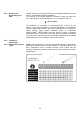
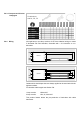
3.13.3 Three-Phase
Operation
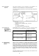
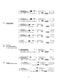
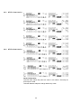
Tthe proper connection of the N conductor is very important in an
installation for even load distribution in a three-phase operation.
The following diagram shows both the correct and the faulty wiring and ist
possible impact:
• U
N
* > U
N
• Theoretical maximum value:
U
N
*max = U
N
x √3 (= 400 VAC @ U
N
= 230 VAC)
• In practice:
U
N
* < 350 V in most cases
(no complete asymmetrical load distribution)
3.13.4 Resistance to
Overvoltage for
QUICKTRONIC
®
for
T5/∅ 16 mm-
Fluorescent Lamps
QUICKTRONIC
®
-ECG for operation of T5/∅ 16 mm- fluorescent lamps
FH
®
...HE and FQ
®
...HO have the following resistance to overvoltage:
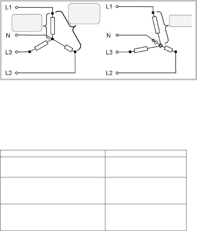
Resistance to overvoltage
QUICKTRONIC
®
INTELLIGENT, QTi
350V Î continuous
400V Î 48 hours
QT-FH ... CW (30 mm height)
QT-FQ ... CW (30 mm height)
300V Î continuous
320V Î 48 hours
350V Î 2 hours
QT-FH ... F/CW (21 mm height)
QT-FQ ... F/CW (21 mm height)
300V Î continuous
320V Î 48 hours
350V Î 2 hours
3.14 Inrush Current /
Automatic Circuit
Breakers
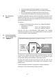
When an ECG is switched on, a starting current pulse of very short
duration (< 1 ms) occurs as the storage capacitors responsible for internal
power supply charge up. If a large number of ECGs are switched on
simultaneously (particularly if they are switched on at peak rated voltage) a
starting current will flow that will reduce the recommended number of ECGs
per automatic circuit breaker below that which would apply if we were to
consider only their rated currents. All switching equipment and protection
devices must therefore be selected according to their current carrying
capacity.
The values mentioned in Section 7.3 refer solely to the automatic circuit
breakers type B from Siemens.
U
N
(z.B. 230V~)
U
phase-Phase
= U
N
x √3
(z.B. 400V~)
U
N
* > U
N