
Service manual


QT-CD121
– 4 –
1 Rear Cabinet 1. Screw ................. (A1) x10 4-1
2. Socket .................. (A2) x1 4-2
2 Top Cabinet 1. Knob ..................... (B1) x1 4-2
(with CD Mechanism/
2. Screw ................... (B2) x3
Tape Mechanism/ 3. Socket .................. (B3) x1
Main PWB)
3 Main PWB/ 1. Screw ................... (C1) x8 4-3
Switch PWB/ 2. Socket .................. (C2) x4 4-3,4-4
Headphones PWB
4 Tape Mechanism 1. Screw ................... (D1) x4 4-4
5 CD Mechanism 1. Screw ................... (E1) x3 4-4
6 Terminal PWB 1. Screw ................... (F1) x5 4-5
2. Hook ..................... (F2) x1
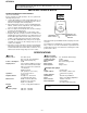
DISASSEMBLY
Caution on Disassembly
Follow the below-mentioned notes when disassembling the
unit and reassembling it, to keep it safe and ensure excellent
performance:
1. Take cassette tape and compact disc out of the unit.
2. Be sure to remove the power supply plug from the wall
outlet before starting to disassemble the unit.
3. Take off nylon bands or wire holders where they need be
removed when disassembling the unit. After servicing the
unit, be sure to rearrange the leads where they were
before disassembling.
4. Take suffcient care on static electricity of integrated
circuits and other circuits when servicing.
STEP REMOVAL PROCEDURE FIGURE
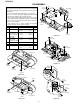
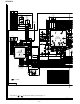
Figure 4-4
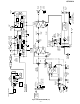
Figure 4-3
Figure 4-5
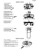
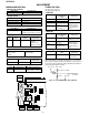
Figure 4-1
(A1)x3
ø3x12mm
(A1)x1
ø3x12mm
(A1)x6
ø3x20mm
Rear Cabinet
Front Cabinet
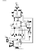
(B2)x3
ø3x10mm
(A2)x1
(B3)x1
Front Cabinet
Top Cabinet
(B1)x1
Main PWB
Headphones
PWB
(C1)x7
ø3x10mm
(C2)x1
Switch PWB
(C1)x1
ø3x10mm
Main PWB
Top Cabinet
Headphones
PWB
Figure 4-2
Top Cabinet
Tape
Mechanism
CD Mechanism
(E1)x3
ø2.5x10mm
(D1)x4
ø3x10mm
(C2)x2
(C2)x1
(F1)x2
ø3x10mm
(F1)x2
ø3x10mm
Terminal PWB
Driver
Push
(F2)x1
(F1)x1
ø3x12mm
Spacer PWB