
Service manual


QT-CD131/131C
A
B
C
D
E
F
G
H
1
23456
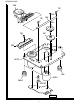
Figure 6 CABINET EXPLODED VIEW
– 6 –
NOTE: The parts of cassette mechanism which are supplied are only the unit and consumable parts.
239
233
608
L3
CD
MECHANISM
Silicon
Grease
213
203
PWB-A3
601x2
603x2
236
603
601
202
214
221
230x2
603
601
231
211
602x6
601x3
215
212
606
601
x3
SW761
250
245
222
228
227
226
225
224
244
223
229
607x2
603x4
241 (241-1, 241-2
241-3, 241-4, 241-5,
241-6, 241-7)
603
604x3
605x3
603x4
201
219
238
LCD701
235
218
607
PWB-A2
601x2
603x5
603
603x4
210
206
208
209
PWB-A1
PWB-B2
PWB-B1
232-1
232-2
207
217
PWB-B3
PWB-B4
PWB-A5
PWB-A4
240
242
232
603
601
x2
243
607
SO651
249
246
LCD501
248
T601
SP501
SP502
C ONLY
IC203
IC202
247