
Service manual


QT-CD131/131C
– 6 –
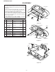
MECHANISM SECTION
• Driving Force Check
PLAY: TW-2412 Over 120 g
Torque Meter
Specified Value
• Torque Check
Torque Meter
Specified Value
Play: TW-2111 25 to 65 g.cm
Fast Forward: TW-2231 60 to 130 g.cm
Rewind: TW-2231 60 to 130 g.cm
• Tape Speed
MTT-111 In motor 3,000 ± 90 Hz Output: Speaker
Teaminal
(CNP201 Load
resistance: 8 ohms)
Instrument
Connection
Specified
Value
Test
Tape
TAPE SECTION
Position of each switch or control
Volume control Max
Function switch Tape/Power Off
X-BASS On
• Bias Oscillation
Adjustment Point
• Playback Amplifier Sensitivity Check
Instrument Connection
Test Tape
MTT-118 1.8 V ± 3 dB Speaker Terminal
(Load resistance: 8 ohms)
Specified Value
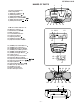
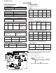
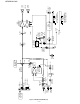
ADJUSTMENT
Figure 6-2 ADJUSTMENT POINTS
• Head Azimuth
Torque Meter
Specified Value
MTT-114 Output: Speaker Terminal
(CNP201 Load resistance: 8 ohms)
Adjusting
Point
Specified Value
Instrument
Connection
L301 82 kHz ± 6 kHz Pin 2 of CNP201
– 6 kHz
fL: Low-range frequency
fH: High-renge frequency
IF 450 kHz 1,720 kHz T3 *1
Band — 530 kHz (fL): L4 *3
Coverage 1.0 ± 0.1 V
Tracking 600 kHz 600 kHz (fL): L3 *2
1,400 kHz 1,400 kHz (fH):TC1
Test Stage
Frequency Frequency
Display
Setting/
Adjusting
Parts
Instrument
Connection
TUNER SECTION
• FM RF
Signal generator: 1 kHz, 75 kHz dev., FM modulated
Band — 87.5 MHz (fL): L2 *1
Coverage 2.0 ± 0.1 V
RF 90.0 MHz 90.0 MHz L1 *2
(10~30 dB)
Test Stage
Frequency
Frequency
Display
Setting/
Adjusting
Parts
Instrument
Connection
*1. Input: Antenna, Output: TP1
*2. Input: Antenna, Output: Speaker Terminal
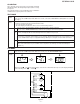
• Detection
Signal generator: 10.7 MHz, FM sweep generator
IF 10.7 MHz 98.00 MHz T1(Turn Input: Pin 1 of
the core of IC1
T1 fully Output: TP2
counter-
clockwise.
Test
Stage
Frequency
Frequency
Display
Setting/
Adjusting
Parts
Instrument
Connection
*1. Input: Antenna, Output: Pin19 of IC2
*2. Input: Antenna, Output: Speaker Terminal
*3. Input: Input is not connected, Output: TP1
• AM IF/RF
Signal generator: 400 Hz, 30%, AM modulated
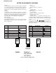
• VCO Frequency
Specified
Value
Instrument
Connection
VR1 76 kHz ± 200 Hz Pin 13, pin 21 and
ground of IC2
Adjusting Point
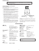
Note:
After preparing the test circuit shown in Fig. 6-1, connect the
Pin 13, Pin 21 and ground of the IC2 with the test circuit, and
measure the value. At this time, apply a standard unmodulated
signal input and adjust the VCO.
Figure 6-1 VCO FREQUENCY TEST CIRCUIT
Pin 13 of IC2 Pin 21 of IC2
D
G
S
10 kohm
TO FREQUENCY
COUNTER
FET : 2SK19 or 2SK54
1
1
VCO
VR1
IC2
T3
L4
L2
IC1
L1
FM IF
T1
TC1
AM TRACKING
L3
AM BAR
ANTENNA
FM ROD ANTENNA
FM BAND
COVERAGE
T2
AM IF
TP2
FM RF
FM DET.
TP1
13
17
19
21
R26
R7
AM BAND
COVERAGE
MAIN PWB
fL fH