
Service manual


QT-CD161/141
– 9 –
NOTES ON SCHEMATIC DIAGRAM
1. Tuner
( ): AM mode
Marking except for ( ): FM mode
2. CD
( ): Play mode
Marking except for ( ): Stop state
3. Deck section
( ): Record mode
Marking except for ( ): Playback mode
Display / Control section:
( ): Active state
Marking except for ( ): CD Function mode at stop state
• Schematic diagram and Wiring Side of P.W.Board for this
model are subject to change for improvement without prior
notice.
• Parts marked with “ ” ( ) are important for
maintaining the safety of the set. Be sure to replace these
parts with specified ones for maintaining the safety and
performance of the set.
• Resistor:
To differentiate the units of resistors, the symbol as K and M
are used: the symbol K means 1000 ohm and the symbol M
means 1000 kohm and the resistor without any symbol is an
ohm resistor. The resistor designated "Fusible" is a fuse type
resistor
• Capacitor:
To indicate the unit of capacitor, a symbol P is used: this
symbol P means micro-micro-farad and the unit of the capacitor
without such a symbol is microfarad. As to electrolytic capacitor,
the expression “capacitance/withstand voltage” is used.
(CH), (TH), (RH), (UJ): Temperature compensation
(ML): Mylar type
(P.P.): Polypropylene type
• The indicated voltage in each section is the one measured by
Digital Multimeter between such a section and the chassis
with no signal given.
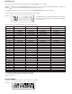
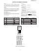
SW102 RECORD/PLAYBACK PLAYBACK
SW201 FUNCTION/POWER TAPE—TUNER— CD/
OFF—ON
SW202 X-BASS OFF—ON
SW501 TUNER UP OFF—ON
SW502 TUNER DOWN OFF—ON
SW503 BAND OFF—ON
REF. NO DESCRIPTION POSITION
SW504 MEMORY OFF—ON
SW505 PRESET DOWN OFF—ON
SW506 PRESET UP OFF—ON
SW507 CD LID OPEN/CLOSE OFF—ON
SW601 TAPE MAIN OFF—ON
SW702 PICKUP IN OFF—ON
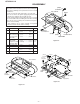
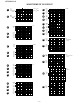
Figure 9 TYPES OF TRANSISTOR
REF. NO DESCRIPTION POSITION
KTA1266 GR
KTA1273 Y
KTC3194 Y
KTC3199 GR
KTC8050 D
KRA102 M
KRA109 M
KRC104 M
KRC107 M
FRONT
VIEW
E C B
(S)(G)(D)
(1) (2) (3)