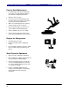
Operator’s Manual Series VII 6113, 6116, 6318, 6320, 6323, 6325 & 6328 Field Cultivator, Rigid Hitch (Constant Level) ! Read the operator’s manual entirely. When you see this symbol, the subsequent instructions and warnings are serious - follow without exception. Your life and the lives of others depend on it. 00274 Cover illustration may show optional equipment not supplied with standard unit.
Great Plains Mfg., Inc. Table of Contents First Page ► Table of Contents Important Safety Information .......................... 1 Safety Rules................................................... 6 Safety Decals ................................................ 7 Introduction ........................................................ 12 Description of Unit ........................................ 12 Using this Manual ........................................ 12 Definitions.....................................
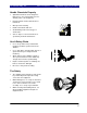
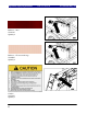
Great Plains Mfg., Inc. Table of Contents ► Important Safety Information Important Safety Information Look for Safety Symbol The SAFETY ALERT SYMBOL indicates there is a potential hazard to personal safety involved and extra safety precaution must be taken. When you see this symbol, be alert and carefully read the message that follows it.
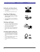
Important Safety Information Table of Contents ► Great Plains Mfg., Inc. Be Familiar with Safety Decals • Read and understand “Safety Decals,” page 7, thoroughly. • Read all instructions noted on the decals. Keep Riders Off Machinery • Riders obstruct the operator’s view. Riders could be struck by foreign objects or thrown from the machine. • Never allow children to operate equipment. • Keep all bystanders away from machine during operation.
Great Plains Mfg., Inc. Table of Contents ► Important Safety Information Transport Machinery Safely Maximum transport speed for implement is 20 mph. Some rough terrains require a slower speed. Sudden braking can cause a towed load to swerve and upset. • Do not exceed 20 mph. Never travel at a speed which does not allow adequate control of steering and stopping. Reduce speed if towed load is not equipped with brakes. • Comply with state and local laws.
Important Safety Information Table of Contents ► Great Plains Mfg., Inc. Practice Safe Maintenance • Understand procedure before doing work. Use proper tools and equipment. Refer to this manual for additional information. • Work in a clean, dry area. • Lower the Series VII Field Cultivator, put tractor in park, turn off engine, and remove key before performing maintenance. • Make sure all moving parts have stopped and all system pressure is relieved. • Inspect all parts.
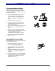
Great Plains Mfg., Inc. Table of Contents ► Important Safety Information Handle Chemicals Properly • Agricultural chemicals can be dangerous. Improper use can seriously injure persons, animals, plants, soil and property. • Read and follow chemical manufacturer’s instructions. • Wear protective clothing. • Handle all chemicals with care. • Avoid inhaling smoke from any type of chemical fire. • Store or dispose of unused chemicals as specified by chemical manufacturer.
Important Safety Information Table of Contents ► Great Plains Mfg., Inc. Safety Rules • Thoroughly read and understand the instructions in this manual before operation. Read all instructions noted on the safety decals. • Be familiar with all Series VII Field Cultivator functions. • Operate machinery from the driver’s seat only. • Do not leave Series VII Field Cultivator unattended with tractor engine running.
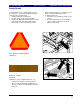
Great Plains Mfg., Inc. Table of Contents ► Important Safety Information Safety Decals Your implement comes equipped with all safety decals in place. They were designed to help you safely operate your implement. • Read and follow decal directions. • Keep all safety decals clean and legible. • Replace all damaged or missing decals. Order new decals from your Great Plains dealer. Refer to this section for proper placement.
Important Safety Information Table of Contents ► Great Plains Mfg., Inc.
Great Plains Mfg., Inc.
Important Safety Information Table of Contents ► Great Plains Mfg., Inc.
Great Plains Mfg., Inc.
Introduction Table of Contents ► Great Plains Mfg., Inc. Introduction Great Plains welcomes you to its growing family of new product owners. This implement has been designed with care and built by skilled workers using quality materials. Proper assembly, maintenance and safe operation will help you get years of satisfactory machine use from your machine. To ease the assembly task and produce a properly working machine, read this entire manual before assembling or setting up new equipment.
Great Plains Mfg., Inc. Table of Contents ► Introduction Assembly and Setup Assistance To order additional copies of operator’s and parts manuals, write to the following address. Include model numbers in all correspondence. If you do not understand any part of this manual or have other assembly or setup questions, assistance is available. Contact Product Support Great Plains Mfg. Inc.
Section 1: Assembly Table of Contents ► Great Plains Mfg., Inc.. Assembly This section covers the proper assembly of the implement. The reference numbers on the figures give you an indication of the order of assembly. For a complete breakdown of any part not shown in this assembly section, refer to the parts manual for proper location. Refer to the Appendix for proper bolt torque values.
Great Plains Mfg., Inc. Table of Contents ► Section 1: Assembly 6113 & 6116 Wing Frame Assembly Bolt the wing frame (1), Figure 2, to the center frame with two 1 x 6 hex bolts (2) with nylon lock nuts. Install the 5/8 x 3 x 5 1/2 u-bolts (3) to secure the wing frame rigid. Use lock washers and hex nuts. On model 6116, bolt the 11” bolt on stub (4) and the 5” bolt on stub (5) to the wing frame using 5/8 x 1 1/2 hex bolts (6), using lock washers and hex nuts.
Section 1: Assembly Table of Contents ► Great Plains Mfg., Inc.. 6318–6328 Inside Wing and Wheel Arm Assembly Bolt the inside wing frames (1) Figure 3, to the center frame with two 1 x 6 hex bolts (2) with nylon lock nuts (3). Draw the nuts down tight but do not torque. Once the wings are attached, insert the wheel arm bracket (4) into the wing frame hangers and secure it just as you did on the center with 1 1/4 x 6 pins (5). Secure the 1 1/4 x 6 pins with the 3/8 x 2 1/4 GR 8 hex bolts (6) & lock nuts.
Great Plains Mfg., Inc. Table of Contents ► Section 1: Assembly Brace Bar and Wing Brace Assembly Install the 1 x 7 1/2 eye bolt (1) Figure 4, in the mounting bracket at the back of the wing with a 1” jam nut on each side of the bracket. Install the rephasing wing cylinder (2) between the eyebolt and the lever on the wheel bracket (see Section 2 Hydraulics for cylinder size). Secure the cylinder with 1” clevis pins, 1” machine washers and 3/16 x 2 cotter pins.
Section 1: Assembly Table of Contents ► Great Plains Mfg., Inc.. Center Truss, Hitch and Strut Assembly Bolt the two center frame trusses (1) Figure 5, to the top side of the center frame and brace bar. Use 3/4 x 2 bolts (3) on the front plates and 5/8 x 1 1/2 bolts (2) on the rear two plates. Use lock washers and hex nuts on all of these bolts. Slide the back of the hitch (4) between the plates at the front of the brace bar as shown.
Great Plains Mfg., Inc. Table of Contents ► Section 1: Assembly Hitch Tongue, Side Plate and Level Bar Assembly Slide the H-bracket (1) down over the hitch pole as shown in Figure 6. Bolt in place with a 3/4 x 6 bolt (2) and lock nut. Draw this nut up but do not torque, as this part must pivot. Attach the level bar cylinder mount (3) to the H-bracket (1) with a 1 X 9 Gr.8 hex bolt (4) with a 1” nylon lock nut do not torque.
Section 1: Assembly Table of Contents ► Great Plains Mfg., Inc.. Center Lift Cylinder, Bolt on Stubs and Hydraulic Valves Assembly Connect the center master cylinder (1) to the hitch frame as in Figure 7. Connect the rod end to the level bar cylinder mount and the H-bracket. Place two 1” flat washers on the inside of the cylinder clevis. Use the 1 x 9 GR8 bolt (2) and nylon lock nut but do not torque.
Great Plains Mfg., Inc. Table of Contents ► Section 1: Assembly Fold Cylinders and Rocker Arm Assembly Connect the center fold cylinders (1) to the center fold bracket as shown in Figure 8. Use the 1” x 3 1/2 clevis pin (2) with 1” machine washer and 3/16 x 2 cotter pin. Attach the rocker (3) to rocker bracket with 1 x 3 Headed Pin (4) using 1” machine washer and 3/16 x 2 cotter. Do Not Connect Rod End Of Cylinders To Rockers Before They Are Charged With Oil.
Section 1: Assembly Table of Contents ► Great Plains Mfg., Inc.. Center Wing Stop / Rear Jack Stand Assembly U-bolt the center wing stop (1) to the second bar from the rear on the center frame as shown in Figure 9. Use 1/2 x 3 x 5 u-bolts (2) with lock washers and hex nuts. Center the wing stop from side to side. Insert the 1/2 x 4 1/2 transport lock quick pins (3) in the holders on the wing stop. Insert the rear stand leg (4) into the frame mount bracket (5) as shown in Figure 9.
Great Plains Mfg., Inc. Table of Contents ► Section 1: Assembly Completing Setup Install the plastic end caps into the open ends of all the 4x3 frame tubes. You should now be ready to add shanks to the machine and then if the machine has a finishing attachment you would install it following the shanks. See the shank layout section 3 for proper shank locations for your unit. Section 5 in the parts manual shows the individual shank assemblies and parts for both the K-flex and magnum shanks.
Section 2: Hydraulics Table of Contents ► Great Plains Mfg., Inc.
Great Plains Mfg., Inc.
Section 3: Shank Placement Table of Contents ► Great Plains Mfg., Inc.
Great Plains Mfg., Inc.
Section 3: Shank Placement Table of Contents ► Great Plains Mfg., Inc.
Great Plains Mfg., Inc.
Section 3: Shank Placement Table of Contents ► Great Plains Mfg., Inc.
Great Plains Mfg., Inc.
Section 3: Shank Placement Table of Contents ► Great Plains Mfg., Inc.
Great Plains Mfg., Inc. Table of Contents ► Section 4: Operating and Maintenance Operating and Maintenance Prior to Going to the Field 1. Both dealer and customer read and thoroughly understand all safety recommendations. (These are found in the Safety Section of this operator manual.) 2. Make sure your tractor horsepower matches the implement you are pulling. This is important so the implement can do the best possible job. Again check for hydraulic leaks and tighten or replace if necessary. 8.
Section 4: Operating and Maintenance Table of Contents ► 10. On the floating hitch field cultivators the front wheels are used to level the machine also. These are adjusted up and down with a turnbuckle on each wheel. (Shorten to lower front end, lengthen to raise front end). Again, the front should be slightly lower than the rear. 11. Check safety chain hookup. Made sure all warning lights are hooked up and functioning correctly. 12.
Great Plains Mfg., Inc. Table of Contents ► drag easier by changing the angle of the first row of teeth. Always make sure that the drag is never pulling off the hang chains. If so, shorten pull chains. b.) On coil tine drags, start with the top eyebolt (12) centered. Then level drag mainframe (4R and 4L) by changing position of leveling bolt (21). There are two holes in the arm and four in the mainframe. One of these will get you where you need to be to level.
Section 4: Operating and Maintenance Table of Contents ► Great Plains Mfg., Inc. Maintenance and Lubrication 1. Always use the transport lock when working or doing maintenance on the Field Cultivator. If folded, be sure your wing stop pins are in place. Read and understand all safety decals on your equipment. 2. During the first season of operation, and periodically after that, check your bolts for tightness.
Great Plains Mfg., Inc. Table of Contents ► Section 5: Specifications and Capacities Specifications and Capacities 3-Section Field Cultivator Specifications Model No.
Appendix Table of Contents ► Great Plains Mfg., Inc.
Great Plains Mfg., Inc. Table of Contents ► Appendix Warranty Great Plains Manufacturing, Incorporated warrants to the original purchaser that this tillage equipment will be free from defects in material and workmanship for a period of one year from the date of original purchase when used as intended under normal service conditions for personal use; 90 days for commercial or rental purposes.