
Service manual


8
R-216FS
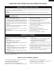
DOOR REPLACEMENT
10
5
4
8
7
9
11
3
2
1
Choke Cover
Door Frame
Putty Knife
6
GRAPHIC SHEET AND MEMBRANE SWITCH REPLACEMENT
Removal
1. Disconnect the power supply cord and then remove
outer case.
2. Open the door and block it open.
3. Discharge high voltage capacitor.
4. Remove the control panel assembly, referring to chapter
of CONTROL PANEL ASSEMBLY REMOVAL.
5. Remove the three (3) screws holding the control unit to
the control panel frame. And remove the control unit.
6. Remove the rubber connector from the long slit on the
control panel frame.
7. Tear away the graphic sheet from the control panel
frame.
8. Tear away the membrane switch from the control panel
frame.
Installation
1. Remove remaining adhesive on the control panel frame
surfaces with a soft cloth soaked in alcohol.
2. Tear the backing paper from the new membrane switch.
3. Insert the ribbon cable of the membrane switch into the slit
of the control panel frame.
4. Adjust the upper edge and right edge of the membrane
switch to the small depression on the surface of the
control panel frame.
5. Attach the membrane switch to the control panel frame by
rubbing with a soft cloth not to scratch.
6. Tear the backing paper from the new graphic sheet.
7. Adjust the upper edge and right edge of the graphic sheet
to the large depression on the surface of the control
panel frame.
8. Attach the graphic sheet to the control panel frame by
rubbing with a soft cloth not to scratch.
9. Tear the small backing paper from the ribbon cable of the
membrane switch.
10. Insert the two (2) holes of the ribbon cable into the two
(2) pins of the control panel frame (rear side).
11. Attach the ribbon cable to the control panel frame rear
side.
12. Place the edge of the membrane switch’s ribbon cable
on the lower portion of the liquid crystal display.
13. Insert the rubber connector into the long slit on the
control panel frame.
14. Reinstall the control unit to the control panel frame with
the three (3) screws.
NOTE:
Do not contact the conductor portion of the ribbon
cable (edge) and the rubber connector directly with
your fingers. This is to avoid oxidized.
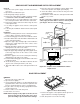
Figure C-2. Graphic Sheet and Membrane Switch
Replacement
REMOVAL
1.
Disconnect the power supply cord.
2. Open the door slightly.
3. Insert a putty knife (thickness of about 0.5mm) into the
gap between the choke cover and corner portion of door
panel as shown in Figure C-5 to free engaging parts.
4. Pry the choke cover by inserting a putty knife in order
shown in figure C-5.
5. Release choke cover from door panel.
6. Now choke cover is free.
NOTE: When carrying out any repair to the door, do not
bend or warp the slit choke (tabs on the door
panel assembly) to prevent microwave leakage.
Figure C-5. Door Disassembly
7. Release two (2) pins of door panel from two (2) holes of
upper and lower oven hinges by lifting up.
8. Now, door panel is free from oven cavity.
Rubber connector
Conductor portions
Ribbon cable
of membrane
switch
Liquid crystal
display
Control panel frame
(Rear side)
Long slit
Pin
Graphic sheet
Membrane
switch
Small
depression
Small backing
paper
Ribbon
cable
Control panel frame
Slit