
User Manual
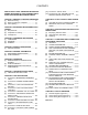
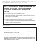
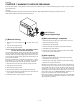
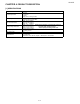
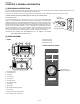
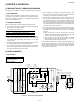
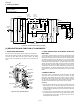
Table Of Contents
- PRECAUTIONS TO BE OBSERVED BEFORE AND DURING SERVICING TO AVOID POSSIBLE EXPOSURE TO EXCESSIVE MICROWAVE ENERGY
- WARNING TO SERVICE PERSONNEL
- MICROWAVE MEASUREMENT PROCEDURE
- FOREWORD AND WARNING
- PRODUCT DESCRIPTION
- GENERAL INFORMATION
- OPERATION
- TROUBLESHOOTING GUIDE
- TEST PROCEDURES
- [1] Procedure A: MAGNETRON ASSEMBLY TEST
- [2] Procedure B: POWER TRANSFORMER TEST
- [3] Procedure C: HIGH VOLTAGE RECTIFIER TEST
- [4] Procedure D: HIGH VOLTAGE CAPACITOR TEST
- [5] Procedure E: THERMAL CUT OUT TEST
- [6] Procedure F: SECONDARY INTERLOCK SWITCH TEST
- [7] Procedure F: PRIMARY INTERLOCK SYSTEM TEST
- [8] Procedure G: MONITOR SWITCH TEST
- [9] Procedure H: BLOWN MINITOR FUSE TEST
- [10] Procedure I: NOISE FILTER TEST
- [11] Procedure J: CONTROL PANEL ASSEMBLY TEST
- [12] Procedure L: RELAY TEST
- [13] Procedure M: FOIL PATTERN ON THE PRINTED WIRING BOARD TEST
- TOUCH CONTROL PANEL ASSEMBLY
- PRECAUTIONS FOR USING LEAD-FREE SOLDER
- COMPONENT REPLACEMENT AND ADJUSTMENT PROCEDURE
- [1] WARNING
- [2] OUTER CASE REMOVAL
- [3] POWER TRANSFORMER REMOVAL
- [4] HIGH VOLTAGE RECTIFIER ASSEMBLY AND HIGH VOLTAGE CAPACITOR REMOVAL
- [5] MAGNETRON REMOVAL
- [6] CONTROL PANEL ASSEMBLY REMOVAL
- [7] OVEN LAMP AND LAMP SOCKET REMOVAL
- [8] POSITIVE LOCK CONNECTOR (NO-CASE TYPE) REMOVAL
- [9] ANTENNA MOTOR REMOVAL
- [10] COOLING FAN MOTOR REMOVAL
- [11] POWER SUPPLY CORD REPLACEMENT
- [12] DOOR SENSING SWITCH/SECONDARY INTERLOCK SWITCH AND MONITOR SWITCH REMOVAL
- [13] DOOR SENSING SWITCH/SECONDARY INTERLOCK SWITCH AND MONITOR SWITCH ADJUSTMENT
- [14] DOOR PARTS REMOVAL
- [15] ANTENNA MOTOR SHAFT REPLACEMENT
- [16] INSTALLATION OF CERAMIC SHELF
- CIRCUIT DIAGRAMS
- Parts List

R21LCF
6 – 1
R21LCF
Service Manual
CHAPTER 6. OPERATION
[1] DESCRIPTION OF OPERATING SEQUENCE
The following is a description of component functions during oven operation.
1. OFF CONDITION
Closing the door activates door sensing switch and secondary inter-
lock switch. (In this condition, the monitor switch contacts are opened.)
When oven is plugged in, 120 volts A.C. is supplied to the noise filter
and the control unit (Figure O-1).
2. COOKING CONDITION
When the Light Up Dial is turned, the following operations occur:
1) The contacts of the relays are closed and components connected
to the relays are turned on as follows.
(For details, refer to Figure O-2)
2) 120 volts A.C. is supplied to the primary winding of the power trans-
former and is converted to about 3.2 volts A.C. output on the fila-
ment winding, and approximately 2150 volts A.C. on the high
voltage winding.
3) The filament winding voltage heats the magnetron filament and the
H.V. winding voltage is sent to a voltage doubler circuit.
4) The microwave energy produced by the magnetron is channelled
through the waveguide into the cavity feed-box, and then into the
cavity where the food is placed to be cooked.
5) Upon completion of the cooking time, the power transformer, oven
lamp, etc. are turned off, and the generation of microwave energy
is stopped. The oven will revert to the OFF condition.
6) When the door is opened during a cook cycle, monitor switch, door
sensing switch, secondary interlock switch, relay (RY2) and pri-
mary interlock relay (RY1) are activated with the following results.
The circuits to the antenna motor, the cooling fan motor, and the
high voltage components are de-energized, the oven lamp remains
on, and the digital read-out displays the time still remaining in the
cook cycle when the door was opened.
7) The monitor switch electrically monitors the operation of the sec-
ondary interlock switch and control relay (RY1) and is mechanically
associated with the door so that it will function in the following
sequence.
a) When the door opens from the closed position, the primary
interlock relay (RY1) and secondary interlock switch open their
contacts. Then the monitor switch contacts close.
b) When the door is closed from the open position, the monitor
switch contacts open first. Then the contacts of the secondary
interlock switch and door sensing switch close.
If the secondary interlock switch and primary interlock relay (RY1) fail
with the contacts closed when the door is opened, the closing of the
monitor switch contacts will form a short circuit through the monitor
fuse, secondary interlock switch, and primary interlock relay(RY1),
causing the monitor fuse to blow.
[2] OVEN SCHENATIC
1. Off Condition
Figure O-1. Oven Schematic-Off Condition
RELAY CONNECTED COMPONENTS
RY-1 oven lamp/antenna motor/fan motor
RY-2 power transformer
SCHEMATIC
NOTE: CONDITION OF OVEN
1. LIGHT UP DIAL OFF.
2. DOOR CLOSED.
FUSE
LINE CROSS CAPACITOR 0.22μF AC250V
NOISE SUPPRESSION COIL
LINE BYPASS
CAPACITOR
0.0033μF / AC 250V
LINE BYPASS
CAPACITOR
0.0033μF / AC 250V
20A
NOISE FILTER
NL
AC120V
60 Hz
OL FM AM
OVEN
LAMP
FAN
MOTOR
ANTENNA
MOTOR
POWER
TRANSFORMER
CAPACITOR
1.00 μF
2300V
DOOR SENSING
SWITCH
SECONDARY
INTERLOCK SWITCH
CONTROL UNIT
THERMAL
CUT-OUT
125ºC (OVEN)
THERMAL
CUT-OUT
145ºC (MAG.)
PRIMARY
INTERLOCK
RELAY
COOK
RELAY
MONITOR SWITCH
MAGNETRON
RECTIFIER
RY1
RY2
A5
A3 A1