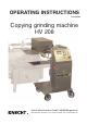
OPERATING INSTRUCTIONS translation Copying grinding machine HV 208 Knecht Maschinenbau GmbH • 88368 Bergatreute Witschwender Straße 26 • Tel.
EC Declaration of Conformity in accordance with the EC Directive 98/37/EC, Appendix II A • Machinery 98/37/EC • Electromagnetic Compatibility 89/336/EEC • Low Voltage 73/23/EEC We hereby declare that the machine described in the following complies with the above-mentioned relevant basic health and safety requirements of the corresponding EC directives in terms of its design and construction and in the version placed into the stream of commerce by us.
Manufacturer Knecht Maschinenbau GmbH Witschwender Str. 26 D-88368 Bergatreute Telephone + 4 9 75 27-9 28-0 Fax + 4 9 75 27-9 28-32 E-mail zentrale@knecht-gmbh.de Documents for the owner of the machine Operating Instructions Date of Issue of the Operating Instructions 10 November 2005 Copyright These operating instructions and the operating documents remain the copyrighted property of Knecht Maschinenbau GmbH.
TABLE OF CONTENTS Page 1. IMPORTANT INFORMATION . . . . . . . . . . . . . . . . . . . . . . . . . . . . . . . . . . . . . . . . 6 1.1 1.2 1.3 1.4 1.5 Foreword to the operating instructions . . . . . . . . . . . . . . . . . . . . . . . . Warnings and symbols in the operating instructions . . . . . . . . . . . . Warning signs on / in the grinding machine and their meaning . . . . Type plate and machine number . . . . . . . . . . . . . . . . . . . . . . . . . . . . .
Table of contents 6. COMMISSIONING . . . . . . . . . . . . . . . . . . . . . . . . . . . . . . . . . . . . . . . . . . . . . . . 22 7. CONTROL . . . . . . . . . . . . . . . . . . . . . . . . . . . . . . . . . . . . . . . . . . . . . . . . . . . . . 23 7.1 Using the control panel . . . . . . . . . . . . . . . . . . . . . . . . . . . . . . . . . . . . 23 7.1.1 7.1.2 7.1.3 Control panel . . . . . . . . . . . . . . . . . . . . . . . . . . . . . . . . . . . . . . . . . . . . . . . . . . .
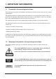
1. IMPORTANT INFORMATION 1.1 Foreword to the operating instructions These operating instructions are intended to familiarise you with the machine and use it for its designated purpose. The operating instructions contain important information on how to operate the machine safely, correctly and cost-effectively. Observing this information helps to avoid dangers, repair costs and downtimes and increase the reliability and service life of the machine.
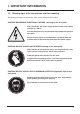
1. IMPORTANT INFORMATION 1.3 Warning signs on/in the machine and their meaning The following warnings and information signs are situated on/in the machine. CAUTION! DANGEROUS ELECTRICAL VOLTAGE (warning on the rear plate) After connection, the power supply of the machine carries lethal voltages (3 x 400 V). Live machine parts may only be opened by authorised specialist personnel. Before carrying out or care, maintenance and repair work, the machine must be disconnected from the mains power supply.
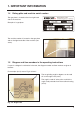
1. IMPORTANT INFORMATION 1.4 Rating plate and machine serial number The type plate is located on the front right-hand side of the machine. Example of a type plate: The machine number is located on the type plate and on the right-hand side of the machine (see arrow). 1.5 Diagram and item numbers in the operating instructions If a part in a diagram is referred to in the text, the diagram number and item number are given in brackets. For example: (3-8/1) means Fig. 3-8/ item 1.
2. SAFETY 2.1 Basic safety information 2.1.1 Observe information in the operating instructions The basic condition for safe handling and trouble-free operation of this machine is knowledge of the basic safety instructions and safety regulations. • The operating instructions contain important information on how to operate the machine safely • These operating instructions, in particular the safety instructions, are to be observed by all persons who work on the machine.
2. SAFETY 2.4.4 Personnel selection, personnel qualification Only trained and instructed personnel may work on the machine. Observe minimum legal age. Responsibilities of the personnel are to be clearly defined for commissioning, operation, maintenance and repair. Personnel still in the training or instruction phase may only be allowed to work on the machine under the permanent supervision of an experienced person. 2.4.
3. DESCRIPTION 3.1 Intended use The copy-grinding machine HV 208 is suitable for the automatic grinding of cutter knives and slicer knives up to a maximum size of 450 mm. 3.2 Height Technical specifications . . . . . . . . . . . . . . . . . . . . . . . . . . . . . . . . . . . . . . . . . . . . . . . . . . . . . . . 1305 mm Width . . . . . . . . . . . . . . . . . . . . . . . . . . . . . . . . . . . . . . . . . . . . . . . . . . . . . . . . . 945 mm Depth . . . . . . . . . . . . . . . . . . . . . . . . .
1305 mm 3. DESCRIPTION 1270 mm 945 mm Fig. 3-1 Dimensions in mm 3.3 Description of functions With the automatic copy-grinding machine HV 208, linear and sickle-shaped knives can be sharpened in combination with the Knecht grinding machine USK 230. The knives are clamped to copygrinding plates and sharpened on the abrasive belt with the automatic copy-grinding machine HV 208. The grinding angle can be set steplessly on the copy-grinding machine.
3. DESCRIPTION 3.4 Description of assemblies 6 5 4 3 2 1 7 Fig.
3. DESCRIPTION 1 2 The copy-grinding plate (3-3/1) contains the information on the cutting edge profile of the knife to be sharpened (3-3/2). A separate grinding plate is required for each knife size and shape. The knife (3-3/2) is fixed on the copy-grinding plate with the locking lever (3-3/3). 4 3 The grinding plate is moved via the guide carriage (3-4-1) of the copy-grinding machine. The movement is limited by the limit switch cam (33/4). Fig.
3. DESCRIPTION 1 The drive unit (3-5/1) with the guide carriage can be swivelled to insert the copy-grinding plate. Fig. 3-5 Drive unit With the compensation weight, the aggressiveness of the abrasive belt which decreases until worn can be compensated for by increasing the grinding pressure. 2 The further the compensation weight is moved away from the abrasive belt, the lower the grinding pressure. The nearer the compensation weight is moved towards the abrasive belt, the higher the grinding pressure.
3. DESCRIPTION By turning the handwheel (3-7/1), the cutting edge angle can be adjusted to the exact degree. 1 Fig. 3-7 Angle adjustment 1 The set grinding angle in degrees can be read off on the angle scale (3-8/1). The angle is read off at the point at which the angle scale protrudes from the machine housing (3-8/2). 2 Fig.
3. DESCRIPTION 2 3 4 The following controls are located on the local terminal: Individual parameters of the selected grinding program are displayed and changed via the control terminal (3-9/1) of the SPS control. 1 7 9 Fig. 3-9 Operating terminal 6 8 5 The required operating mode is selected with the selection switch "Manual Automatic“ for manual or automatic mode (3-9/7).
4. TRANSPORT For transport, the valid local safety and accident prevention regulations must be observed. Only transport the machine with the machine feet facing downwards. CAUTION 4.1 Means of transport For transport and installation of the copy-grinding machine, only use means of transport of a suitable size, e.g. lorry, fork-lift, hydraulic lift truck. When using a fork-lift or lift truck, move the fork under the copy-grinding machine; observe the centre of gravity of the machine. 4.
5. INSTALLATION 5.1 Selection of qualified personnel We recommend that the assembly work on the copy-grinding machine be carried out by trained Knecht personnel. We do not accept liability damage as a result of incorrect assembly. CAUTION 5.2 Installation site When defining the installation site, observe the necessary space requirements for assembly, maintenance and repair work on the machine (see section 3.2). 5.
5. INSTALLATION 5.5 Assembly of copy-grinding machine Install copy-grinding machine on a level surface. Plug in the plug of the grinding machine USK 230. Completely instal and check the safety equipment before commissioning. All guards must be installed and tested for proper operation by a qualified specialist before the machine is started. CAUTION The copy-grinding machine HV 208 must be fitted to a prepared Knecht grinding machine.
5. INSTALLATION 5.6 Calibrate angle scale 6 mm To calibrate the angle scale, a copy-grinding plate is inserted in the machine with the relevant knife. Set the selection switch "Manual / Automatic" to Automatic and press the "Start" button. Check the distance between the abrasive belt and the copy plate. For a grinding angle of 25°, the distance must be 6 mm. Fig. 5-2 Distance After pre-adjusting to approx. 6 mm, set the selection switch to "Manual" and fit a new abrasive belt on the machine USK 230.
6. COMMISSIONING All work may only be carried out by authorised specialist personnel. The valid local safety and accident prevention regulations are to be observed. CAUTION CAUTION Risk of hands, hair and items of clothing being pulled into the grinding machine when it is switched on. Serious injuries are possible. Fig. 6-1 HV 208 Connect the power plug (CEE plug) to the customer's socket on the USK 230 (3x400V, 16A).
7. CONTROL Switching-on sequence: • Switch on main switch (4-2/1) • Unlock "EMERGENCY OFF" button (4-3/10) • Wait for initialisation • Push "CONTROL ON" button, "Control On" lights up, EMERGENCY - OFF switch is activated. 7.1 Using the control panel IMPORTANT The parameters may only be altered by suitably qualified personnel. This personnel must be familiar with the machine functions and the meaning of the parameters. Otherwise, damage to the machine may occur. 7.1.
7. CONTROL 7.1.2 Changing parameters We will describe how to change parameters using the example "NUMBER OF FEEDS" Press button "Feed" (7-2/1) Copy grinding mach. HV208 Lang. Par. Stat. Diag 1 Figure 7-2 No.pos.ops. Grinding cycles 1 Grinding cycles 2 Grinding cycles 3 3 2 1 1 1 Move the cursor to the number next to "NUMBER OF FEEDS" (7-3/1). Enter new value and confirm with "ENTER" (7-3/2). 2 Figure 7-3 For final saving, turn the "PROGRAM SELECTION SWITCH" to a different program and back again.
7. CONTROL Language switching 0 = German 1 = English 2 = Spanish 0 1 Move the cursor (7-5/2) to the Language selection number (7-5/1) and enter the number for the language you want. Confirm with "ENTER" (7-5/3). 3 2 Figure 7-5 7.1.3 Parameters To access the submenu "PAR." (Parameters), press the button 7-6/1. In this submenu you will find all the adjustable parameters of the machine, e.g. "FEED TIME" Copy grinding mach. HV208 Lang. Par. Stat. Diag 1 Figure 7-6 No. pos. ops. Grinding cycles c.
7. CONTROL Parameters in the submenu No. pos. ops. Grinding cycles c.pl. 1: Segment gr. act. 2: Copy cl.plate le. 3: Copy cl.plate ri. 4: Lower copy.pl. 5: Lift c.cl.pl.re 6: Copy cl.pl. l/r 0 0 cyc. 1: No.pos.ops. 2: Grinding cycles 1 3: Grinding cycles 2 4: Grinding cycles 3 5: Grinding cycles 4 6: Grinding cycles 5 7: Grinding cycles 6 8: Grinding cycles 7 9: Grinding cycles 8 10: Grinding cycles 9 11: Grinding cycles 10 12: 1st posit. time 13: Grind. pos. time 14: Cor. v. ret. gr.
7. CONTROL No. pos. ops. Grinding cycles c.pl. 0 0 cyc. Figure 7-9 "Segment gr. on" Segment grinding selected The machine processes knives with several segments one segment after the other.When "Segment grinding on" is set to 0, all segments are ground in one go. “Copy clamping pl. l.” Copy clamping plate left Dwell time of the copy clamping plate on the left until top/bottom change of the polishing units, reverse motion takes place during polishing the knife backs or during grinding.
7. CONTROL “C/pl. raise” Raise copy clamping plate On the cam plate there are pairs of cams, and at the end a cam is mounted to raise the copy clamping plate at the knife corners or at the end. This parameter is changed to reset the raising time when the final position is reached. “Copy pl. l/r” Limit switch monitoring time If, in automatic mode, the copy clamping plate remains at the limit switch for longer than the time set (due to a defective limit switch) the machine switches off.
7. CONTROL No. pos. ops. Grinding cycles c.pl. 0 0 cyc. Figure 7-10 “No. pos. ops.” Number of knife feeds This parameter determines the number of feed cycles. “Grinding cycle 1”...”Grinding cycle 10” The number of grinding cyles is shown in ascending order for each knife processing. The grinding cycles are only valid when the corresponding number of feeds is entered. “1st posit. time” Feed time for first feed “Grind. pos. time” Feed time for the 2nd to 10th feeds “Cor. v. ret. gr.
7. CONTROL 7.2 Program selection Program selection switch (3-9/2) You can use the program selection switch (3-9/2) to select three different programs. 20 data registers are allocated to each switch setting. When you change the switch setting, first the allocation of the old switch position is saved, then the new one is loaded. For each program, the variables are entered in the same data register. 7.3 Manual mode Preconditions for manual mode: • Main switch On • Control On • Protection hood closed 7.3.
7. CONTROL If you release the button during copy clamping plate replacement and then press it again, the copy clamping plate replacement cycle starts again with the movement to the left. If the limit stop of the copy clamping plate on the right is fixed, you can move the copy clamping plate to the left and right by hand when the button is pushed. The first direction of movement after you press the button is always to the left. 7.
7. CONTROL 7.4.2 Starting automatic sequence • • • • Prepare the machine (see Section 6. Assembly) Select Automatic mode Close protection hood if not already closed Push start button Now the cycle runs automatically according to the program selected. Automatic cycle 1. The grinding unit moves forward and applies the set pressure when coolant monitoring is not selected. If coolant monitoring is selected, the grinding unit is only applied when the coolant flow control is activated.
7. CONTROL 7.6Fault and status messages To read fault messages, press the “DIAG” (7-11/1) button Copy grinding mach. HV208 Lang. Par. Stat. Diag 1 Figure 7-11 Diagnosis Control On I/O 1 Figure 7-12 Blade pos. rear front Copy clamp.
7. CONTROL Meaning of the fault messages Only qualified personnel may rectify the causes of system faults that require work on the control system. They must observe the instructions given in the operating instructions for personal, equipment and machine protection during checking of drive components.
8. OPERATION 8.1 General principles of grinding technology Material must be removed in order to resharpen a blunt cutting edge. A sharp cutting edge can be obtained only if the knife/blade is sharpened right to the front of the cutting edge. The only way it is possible to check whether the cutting edge has actually been ground is by the burr. If a burr has occurred at the cutting edge, the grinding operation can be completed at the cutting edge.
8. OPERATION Function Setting range Factory setting By setting the number of feeds, the cutting edge profile can be adapted to the relevant requirements. Feed Feed Feed Feed Feed Feed Feed Feed Number of knife feeds Fig.
For all work on/with the machine, the valid local safety and accident prevention regulations and sections "Safety" and "Important information" in the operating instructions must be observed. CAUTION Fig.
8. OPERATION 2 1 Insert the copy-grinding plate (8-3/1) by pushing it over the guide carriage (8-3/2). Ensure that the copy-grinding plate (8-3/1) is suitable for the knife to be ground. The knife type (8-3/4) is engraved on the copy-grinding plate under the locking lever (8-3/3). 3 4 Risk of injury on the spigot due to fingers, hair and clothing being drawn in. CAUTION Serious injuries possible. Fig.
8. OPERATION Attach the cam for the limit position to the copygrinding plate as shown in Fig. 8-5. The cam defines the end of travel and triggers the movement in the opposite direction. IMPORTANT If the cam for the limit position is not attached, the copy-grinding plate is moved down from the guide carriage and may fall and be damaged. Fig. 8-5 Cam for limit position Insert the knife in the copy-grinding plate and lock the knife with the lever. 1 Sharp knife edge. Serious injuries are possible.
8. OPERATION Swivel the drive unit (8-7/1) into working position and lock the locking lever (8-7/2) of the copygrinding machine. 1 2 Fig. 8-7 Working position 8.4 Setting the compensation weight With the compensation weight, the aggressiveness of the abrasive belt which decreases until worn can be compensated for by increasing the grinding pressure. 2 3 The further the compensation weight is moved away from the abrasive belt, the lower the grinding pressure.
8. OPERATION 8.5 Setting the cutting edge angle By turning the handwheel (8-9/1), the cutting edge angle can be adjusted to the exact degree. 2 The set grinding angle in degrees can be read off on the angle scale (8-9/2). 3 The angle is read off at the point at which the angle scale protrudes from the machine housing (8-9/3). 1 Fig. 8-9 Angle adjustment 8.6 Starting the grinding process 2 4 1 The grinding process can now be started.
9. MAINTENANCE & CARE For all work on the copy-grinding machine, the valid local safety and accident prevention regulations and sections "Safety" and "Important information" in the operating instructions must be observed. CAUTION Only use original replacement and wear parts. If non-OEM parts are used, it is not ensured that they are designed and produced to the necessary load and safety requirements. 9.
10. OPERATIONAL FAULTS Operational fault Fault Remedy The knife does not have a burr Abrasive belt is worn fit new belt Grinding angle is incorrectly set adjust angle or scale (Ch. 5.6) Grinding cycles 1 too low too flat Cutting edge angle on knife extremely steep select higher number (Ch..
11. Disassembly and disposal 11.1 Disassembling the machine 11.2 Disposal After the end of its service life, the machine must be disposed of by a qualified, specialist disposal company. In exceptional cases and after agreement with Knecht Maschinenbau GmbH, you may be able to return it to us. Operating means (e.g. whetstones, grinding belts, coolants) must also be expertly disposed of.
12. Service, spare parts, accessories 12.1 Postal address Knecht Maschinenbau GmbH Witschwender Straße 26 D88368 Bergatreute Phone: Fax: 0 73 27 / 9 28 – 0 0 73 27 / 9 28 – 32 zentrale@knecht.eu www.knecht.eu 12.2 Service Service Department: See postal address service@knecht.eu 12.
12. Service, spare parts, accessories 12.4 Accessories If you need grinding plates, other accessories or parts subject to wear such as grinding belts etc., please contact our sales staff, our sales partners, or Knecht Maschinenbau GmbH directly. Thank you for buying this machine.