
Technical data
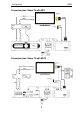
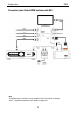


Configuration M203
5
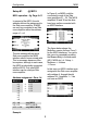
Setup #1 @ M219
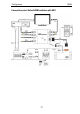
M219 operation - fig. Page 9+11
In respect of the M219, the slot
address defines the assignment to
the Side room amplifier. A M203
can only be connected to an Side
room amplifier within the address
range x1 – x4.
The slot address defines which
Side room amplifier the M203
interface should communicate with.
This is necessary because of the
bus system, although in each case,
the M203 is individually connected
with the M219. Only one M203
interface can be used per Side
room amplifier.
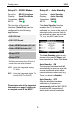
Address assignment : Zone 1-4
M219/ 217 M200/ M203
x 1 Ö x 11
x 2 Ö x 12
x 3 Ö x 13
x 4 Ö x 14
x 5
x 6
x 7
x 8
x 1 – x 4: only M219
x 5 – x 8: M217 or M219
x 11 – x 14: only M200 / M203
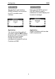
Example
In Figure A, an M203 could be
connected to each of the Side
room amplifiers 31 – 34. The M219
amplifiers 35 and 38 on the other
hand may not be connected with
an M203 interface.
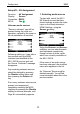
Fig A. Multiroom version list / Zone 3
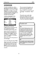
The figure below shows the
Multiroom version list from Zone 3
for the M203 interfaces. You get to
this menu by repeatedly pressing
the Zone softkey in the sub-menu
(M51, M230 etc.) of: Setup Ö
Multiroom Ö Version
Ö Zone x
In this case, an M203 interface was
assigned to the Side room amplifier
with address 4, through the slot
address 314. Amplifiers 1 – 3 do
not have an M203.
Fig B. Multiroom version list / Zone 3