R-22AT R-23AM R-24AT SERVICE MANUAL SX910R24ATK// COMMERCIAL MICROWAVE OVEN MODELS DOUBLE QUANTITY EXPRESS DEFROST 1900W/R-24 AT 11 1 12 2 13 3 14 4 15 5 16 6 17 7 18 8 19 9 20 0 MANUAL/ REHEAT STOP / CLEAR POWER LEVEL START SET CHECK VOLUME R-22AT R-23AM R-24AT R-24AT In interests of user-safety the oven should be restored to its original condition and only parts identical to those specified should be used. TABLE OF CONTENTS Page SERVICING ..............................
R-22AT R-23AM R-24AT SERVICING WARNING TO SERVICE PERSONNEL Microwave ovens contain circuitry capable of producing very high voltage and current. Contact with following parts will result in electrocution. High voltage capacitors, High voltage transformers, Magnetrons, High voltage rectifier assembly, High voltage fuses, High voltage harness. REMEMBER TO CHECK 3D REMEMBER TO CHECK 4R 1) Disconnect the supply. 2) Door opened, and wedged open. 3) Discharge high two voltage capacitors.
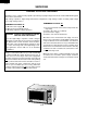
R-22AT R-23AM R-24AT SERVICE MANUAL PRODUCT SPECIFICATIONS GENERAL INFORMATION COMMERCIAL MICROWAVE OVEN APPEARANCE VIEW R-22AT/ R-23AM/ R-24AT GENERAL IMPORTANT INFORMATION This Manual has been prepared to provide Sharp Corp. Service engineers with Operation and Service Information. It is recommended that service engineers carefully study the entire text of this manual, so they will be qualified to render satisfactory customer service.
R-22AT R-23AM R-24AT PRODUCT DESCRIPTION SPECIFICATION ITEM DESCRIPTION Power Requirements Power Comsumption Power Output Case Dimensions Cooking Cavity Dimensions Control Complement for R-22AT/24AT 230 - 240 Volts 50 Hertz Single phase, 3 wire earthed 2.4 kW Approx. 11 A [R-22AT] / 2.9 kW Approx.
R-22AT R-23AM R-24AT APPEARANCE VIEW OVEN 1. 2. 3. 4. 5. 6. 7. 8. 9. 10. 11. 12. 13. 14. 15. 16. 17. 18 19 11 Control panel Hole for safety door latches Ceramic floor Splash cover Oven light Air intake filter Air intake openings 13 Oven cavity Door seals and sealing surfaces Door hinges Oven door with see-through window Door safety latches Door handle.
R-22AT R-23AM R-24AT OPERATION SEQUENCE Closing the door activates all door interlock switches (1st latch switch, 2nd latch switch, 3rd latch switch and stop switch). IMPORTANT 2. When the oven door is closed, the monitor switch contacts COM-NC must be open. When the microwave oven is plugged in a wall outlet (230 - 240 volts, 50Hz), the line voltage is supplied to the point A5+A7 in the control panel through the noise filter. 3. Figure O-1 on page 36 1. The digital display shows . IDLE CONDITION 4.
R-22AT R-23AM R-24AT power, the line voltage is supplied to the high voltage transformers T1+T2 intermittently within a 48 second time base through the contacts of the relays RY3+RY4. The following levels of microwaves power are given. TWO MAGNETRON OPERATION SYSTEM Two magnetrons MG1+MG2 are equipped in order to get higher microwave power output.
R-22AT R-23AM R-24AT FUNCTION OF IMPORTANT COMPONENTS DOOR OPEN MECHANISM CAUTION:BEFORE REPLACING A BLOWN FUSE F2 F6.3A TEST THE 1ST LATCH SWITCH SW1, MONITOR SWITCH SW4 AND MONITOR RESISTOR R1 FOR PROPER OPERATION. (REFER TO CHAPTER “TEST PROCEDURE”). 1. The door release lever is pulled. 2. The upper latch head is lifted up by the linked door release lever. 3. The head lever is lifted up by the door release lever. 4. The joint lever is lifted up by the head lever. 5.
R-22AT R-23AM R-24AT cavity, the oven temperature fuse will open at 120˚C, causing the oven to shut down. The defective temperature fuse must be replaced with new rated one. MAGNETRON THERMISTOR The thermistor is a negative temperature coefficient type. The air temperature around the upper magnetron is detected through the resistance of the thermistor. If the temperature is high, the control panel will display "EE17" and the oven will stop to protect the lower magnetron against overheat.
8 ON CONDITION OFF CONDITION CONDITION “ . “ does not appear on display when power cord is plugged into wall outlet. Control panel can not accept key in. Fuse F2 F6.3A blows when the door is opened. Home fuse blows when power cord is plugged into wall outlet. Fuse F1 F13A blows when power cord is plugged into wall outlet. Oven lamp, fan motor and stirrer motors do not work for 1 minute when the door is opened or after cooking. Fuse F2 F6.3A blows when power cord is plugged into wall outlet.
R-22AT R-23AM R-24AT TEST PROCEDURES PROCEDURE LETTER A MAGNETRON TEST COMPONENT TEST NEVER TOUCH ANY PART IN THE CIRCUIT WITH YOUR HAND OR AN INSULATED TOOL WHILE THE OVEN IS IN OPERATION. CARRY OUT 3D CHECKS. Isolate the magnetron from high voltage circuit by removing all leads connected to filament terminal. To test for an open circuit filament use an ohmmeter to make a continuity test between the magnetron filament terminals, the meter should show a reading of less than 1 ohm.
R-22AT R-23AM R-24AT TEST PROCEDURES PROCEDURE LETTER COMPONENT TEST Room temperature ................................................................................................. T0 = 21°C Initial temperature .................................................................................................. T1 = 11°C Temperature after (28 + 3) = 31 sec [for R-22AT].................................................. T2 = 21°C Temperature after (22 + 3) = 25 sec [for R-23AM/24AT] ........................
R-22AT R-23AM R-24AT TEST PROCEDURES PROCEDURE LETTER COMPONENT TEST B HIGH VOLTAGE TRANSFORMER TEST WARNING: High voltage and large currents are present at the secondary winding and filament winding of the high voltage transformer. It is very dangerous to work near this part when the oven is on. NEVER make any voltage measurements of the high-voltage circuits, including the magnetron filament. CARRY OUT 3D CHECKS. Disconnect the leads to the primary winding of the high voltage transformer.
R-22AT R-23AM R-24AT TEST PROCEDURES PROCEDURE LETTER COMPONENT TEST Table: Terminal Connection of Switch Plunger Operation COM to NO COM to NC Released Depressed Open circuit Short circuit Short circuit Open circuit COM; Common terminal, NO; Normally open terminal NC; Normally close terminal If incorrect readings are obtained, make the necessary switch adjustment or replace the switch. CARRY OUT 4R CHECKS. F FUSE F3, F4 M8A TEST CARRY OUT 3D CHECKS.
R-22AT R-23AM R-24AT TEST PROCEDURES PROCEDURE LETTER J MONITOR RESISTOR R1 TEST COMPONENT TEST CARRY OUT 3D CHECKS. Disconnect the leads from the monitor resistor R1. Using an ohmmeter and set on a low range. Check between the terminals of the monitor resistor R1. The resistance of monitor resistor R1 should be read approx. 4.3Ω. If incorrect readings are obtained, replace the monitor resistor R1. CARRY OUT 4R CHECKS. K THERMISTOR TEST 1. CARRY OUT 3D CHECKS. 2.
R-22AT R-23AM R-24AT TEST PROCEDURES PROCEDURE LETTER COMPONENT TEST Between N and L Approx. 680 kΩ Between terminal N and WHIT Short circuit Between terminal L and BLK Short circuit NOISE FILTER L INDICATION OF OHMMETER N MEASURING POINT F1 : FUSE F13A NOISE SUPPRESSION COIL DISCHARGE RESISTOR 680 kΩ 1/2W LINE CROSS CAPACITOR 0.22µF/ AC250V DISCHARGE RESISTOR 10 MΩ 1/2W LINE CROSS CAPACITOR 10000 pF/ AC250V If incorrect readings are absorbed, replace the noise filter. CARRY OUT 4R CHECKS.
R-22AT R-23AM R-24AT TEST PROCEDURES PROCEDURE LETTER COMPONENT TEST a) When rotating the encoder, the cooking time can not be entered. 3. Control Unit The following symptoms may indicate a defective control unit. Replacing the control unit. Before replacing the control unit, perform the switch unit test (Procedure P) to determine if control unit is faulty. 3-1 Programming problems. a) When touching the buttons, a certain group of buttons do not produce a signal. 3-2 Display problems.
R-22AT R-23AM R-24AT TEST PROCEDURES PROCEDURE LETTER COMPONENT TEST Check voltage at the relay coil with a D.C. voltmeter during the microwave cooking operation. DC. voltage indicated ............................. Defective relay. DC. voltage not indicated ....................... Check diode which is connected to the relay coil. If diode is good, control unit is defective. RELAY SYMBOL OPERATIONAL VOLTAGE RY1 RY3 RY4 APPROX. 19.0V D.C. APPROX. 16.0V D.C. APPROX. 18.0V D.C.
R-22AT R-23AM R-24AT TOUCH CONTROL PANEL ASSEMBLY FOR R-24AT / R-22AT OUTLINE OF TOUCH CONTROL PANEL The touch control section consists of the following units as shown in the touch control panel circuit. This AC voltage is the input to the IN3 and IN5 ports of IC1, which determines if there is a magnetron / high voltage problem. (1) Control Unit (2) Key Unit HIGH VOLTAGE TRANSFORMER The principal functions of these units and the signals communicated among them are explained below.
R-22AT R-23AM R-24AT CONTROL PANEL ASSEMBLY FOR R-23AM OUTLINE OF CONTROL PANEL The control section consists of the following units as shown in the control panel circuit. 11) Exhaust Air Temperature Detecting Circuit This is a circuit for transmitting output change of thermistor (Oven thermistor (1)) to IC1. (1) Control Unit (2) Switch Unit (3) Encoder Unit 12) High Voltage Monitoring Circuit.
R-22AT R-23AM R-24AT Pin No. Signal I/O 2 IN7 IN Temperature measurement input: MAGNETRON THERMISTOR AND OVEN THERMISTOR (2). By inputting DC voltage corresponding to the temperature detected by the thermistor, this input is converted into temperature by the A/D converter built into the LSI. 3 IN6 IN Temperature measurement input: OVEN THERMISTOR (1).
R-22AT R-23AM R-24AT Pin No. Signal I/O 25 P30 OUT 26 CNVSS IN Connected to Vc.(-5V) 27 RESET IN Auto clear terminal. Signal is input to reset the LSI to the initial state when power is supplied. Temporarily set to "L" level the moment power is supplied, at this time the LSI is reset. Thereafter set at "H" level. 28 XIN IN Internal clock oscillation frequency setting input.
R-22AT R-23AM R-24AT Pin No. Signal I/O 45 P11 OUT Segment data signal. Signal similar to P17. Key strobe signal. Signal applied to touch-key section. A pulse signal is input to R0 - R3 terminal while one of G-7 line keys on key matrix is touched. 46 P10 OUT Segment data signal. Signal similar to P17. P07-P06 OUT Segment data signal. Signal similar to P17. P05 OUT Digit selection signal. The relation between digit signal and digit are as follows: Digit signal Digit P05 ...................
R-22AT R-23AM R-24AT Pin No. Signal I/O AN7-AN6 IN Terminal to switch the specification. 7 AN5 IN Connected to GND. 8 AN4 IN A/D input for troubleshooting Magnetron 1. 9 AN3 IN A/D input for troubleshooting Magnetron 2. 10 AN2 IN Temperature measurement input: OVEN THERMISTOR (1). By inputting DC voltage corresponding to the temperature detected by the thermistor, this input is converted into temperature by the A/D converter built into the LSI.
R-22AT R-23AM R-24AT Pin No. Signal I/O 28-29 P71-P70 OUT 30 XIN IN 31 XOUT OUT 32 VSS IN 33 P27 OUT Oven lamp, Blower motor and Stirrer motor driving signal (Square Waveform : 50Hz). During cooking To turn on and off the shut-off relay (RY1). H The Square waveform voltage is delivered to L the RY1 relay driving circuit and relays 20 msec (RY2, RY3, COOK RELAY) control circuit. 34 P26 OUT Terminal not used. P25-P24 OUT Magnetron high-voltage circuit driving signal.
R-22AT R-23AM R-24AT 2-2 Memory IC (IC2) FOR R-24AT / R-22AT AT24C04 is a 4K-bit, serial memory, enabling CMOS to be erased/written electrically. This memory is constructed with 512 registers x 8bits, enabling individual access, read and write operations to be performed. Details of input/output signal for IC2 are as shown in the following diagram. FUNCTIONAL DIAGRAM (3) Vcc (4) Vss H.V.
R-22AT R-23AM R-24AT SERVICING 1. Precautions for Handling Electronic Components This unit uses CMOS LSI in the integral part of the circuits. When handling these parts, the following precautions should be strictly followed. CMOS LSI have extremely high impedance at its input and output terminals. For this reason, it is easily influenced by the surrounding high voltage power source, static electricity charge in clothes, etc, and sometimes it is not fully protected by the built-in protection circuit.
R-22AT R-23AM R-24AT PROCEDURE FOR CHECKING/CLEARING SERVICE COUNTS OF MICROWAVE OVEN FOR R24AT / R-22AT PROCEDURE FOR ENTERING TO IC-2 FOR R24AT / R-22AT When the control unit or IC-2 is exchanged, re-enter the constans of EXPRESS DEFROST, the memory information and the EEPROM data, referring to the following procedures. If not so, the oven will not operate correctly.
R-22AT R-23AM R-24AT PAD ORDER DISPLAY (Door close) • SET • Table of EEPROM data PHONE Memory pad Data "NUMBER" • 3 2 2 3 5 Hiher temperature limit setting of magnetron thermistor detection. 1 NUMBER 1 •0 4 0 0 0 0 Constant setting of fan lock detection. 5 NUMBER 1 •5 6 0 1 0 0 Time setting of fan lock detection. "NUMBER" • 8 3 2 0 0 Hiher temperature limit setting of exhaust air detection. 9 0 0 0 0 Constant setting of fan lock detection.
R-22AT R-23AM R-24AT COMPONENT REPLACEMENT AND ADJUSTMENT PROCEDURE WARNING: Avoid possible exposure to microwave energy. Please follow the instructions below before operating the oven. 1. Disconnect the oven from power supply. 2. Make sure that a definite “click” can be heard when the microwave oven door is unlatched.
R-22AT R-23AM R-24AT 4. Remove the wire lead(s) of high voltage transformer(s) from the wire holder. 5. Pull out the wire lead(s) of high voltage transformer(s) from the tube. 6. Disconnect wire lead(s) of high voltage transformer(s) from high voltage capacitor(s). 7. Disconnect the high voltage fuse(s) from high voltage transformer(s). 8. Disconnect the main wire harness from high voltage transformer(s). 9. Remove two (2) screws holding each power transformer to base plate. 10.
R-22AT R-23AM R-24AT Now, the the high voltage rectifier assembly is free. 8. Remove two (2) screws holding the capacitor holder to oven cavity. Now, the capacitors are free. 2. DO NOT REPLACE ONLY THE HIGH VOLTAGE RECTIFIER. IF IT IS DEFECTIVE, REPLACE THE HIGH VOLTAGE RECTIFIER ASSEMBLY. 3. WHEN REPLACING THE HIGH VOLTAGE RECTIFIER ASSEMBLY AND THE HIGH VOLTAGE CAPACITOR, THE CATHODE (EARTH) SIDE TERMINAL OF THE HIGH VOLTAGE RECTIFIER MUST BE SECURED FIRMLY WITH A EARTHING SCREW. CAUTION: 1.
R-22AT R-23AM R-24AT TERMINAL INSULATOR REPLACEMENT Installation 1. Insert the receptacle into terminal insulator. 2. Close covers of the terminal insulator, as shown illustlated below. 1. Open covers of the terminal insulator by using small flat type screw driver. 2. Remove the receptacle from the terminal insulator. 3. Now, the terminal insulator is free.
R-22AT R-23AM R-24AT for R-22AT and R-24AT 2. When inserting key cable to main body set, ensure them free from caught-in trouble. In addition, when installing the control panel assembly to base plate with screws, be sure of pushing the control panel unit upward to fix with screws firmly. 3. Do not allow any wire leads to come near the varistor works, because it will explode and the wire leads near by the varistor will be damaged. CONTROL UNIT AND CONTROL PANEL FRAME (WITH KEY) 7.
R-22AT R-23AM R-24AT 1. Loosen the two (2) screws holding the latch hook. 2. With the door closed, adjust the latch hook by moving it back and forward, or up and down. In and out play of the door allowed by the latch hook should be less than 0.5mm. The vertical position of the latch hook should be placed where the stop switch and 1st, 2nd, 3rd latch switches have activated with the door closed.
R-22AT R-23AM R-24AT ture, light or sensing of gentle warm air movement around oven door is not abnormal and do not of themselves, indicate a leakage of microwave energy from oven cavity. If such were the case, your oven could not be equipped with a vent, the very purpose of which is to exhaust the vapor-laden air from the oven cavity. around door with an approved microwave survey meter. (Refer to Microwave Measurement Procedure.
R-22AT R-23AM R-24AT MICROWAVE MEASUREMENT After any repair, the microwave oven must be checked for microwave leakage to ensure continued safe operation. BS EN 60335-2-25 specifies that the maximum permitted leakage with a load of 275 ml is 50 W/m2 (equivalent to 5 mW/cm2 ) at a distance of 5 cm from the oven.
N GRN/YLW WHT BM UPPER STIRRER MOTOR OVEN LAMP SW1: 1ST LATCH SWITCH (PRIMARY INTERLOCK SWITCH) 36 SW5: STOP SWITCH TF1: MAGNETRON (MG1) TEMP. FUSE 150 °C TF2: MAGNETRON (MG2) TEMP. FUSE 150°C H.V. FUSE 0.6 A/ 5 kV (R-22AT) 0.75 A/ 5 kV R-24AT R-23AM H.V. FUSE 0.6 A/ 5 kV (R-22AT) 0.75 A/ 5 kV R-24AT R-23AM SW3: 3RD LATCH SWITCH Figure O-2 Oven Schematic-IDLE Condition (Door opened condition) C2: H.V. CAPACITOR F3: FUSE M8A C1: H.V. CAPACITOR C2: H.V.
N GRN/YLW WHT BM UPPER STIRRER MOTOR BLOWER MOTOR OVEN LAMP LOWER STIRRER MOTOR SW1: 1ST LATCH SWITCH (PRIMARY INTERLOCK SWITCH) 37 SW5: STOP SWITCH SW3: 3RD LATCH SWITCH Figure O-3 Oven Schematic-Cooking Condition H.V. FUSE 0.6 A/ 5 kV (R-22AT) 0.75 A/ 5 kV R-24AT R-23AM H.V. FUSE 0.6 A/ 5 kV (R-22AT) 0.75 A/ 5 kV R-24AT R-23AM F3: FUSE M8A C1: H.V. CAPACITOR C2: H.V. CAPACITOR MG1: MAGNETRON H. V. RECTIFIER T1: HIGH VOLTAGE TRANSFORMER TF2: MAGNETRON (2) TEMP.
H 1 CN-B 2 RY-1 TAB3 3 38 4 RY-1 CN-A TAB1 CT1 TAB2 RY-2 5 TAB3 TAB4 RY-3 T IC TAB3 BRN TAB4 BLK CN-A 1 BLK 2 3 PNK 4 5 WHT 6 7 RED COM. COM. NO NO WHT WHT WHT GRN GRN ORG SW5 : STOP SWITCH SW3 : 3RD LATCH SWITCH GRN GRN GRY WHT COM. NO BLK PNK W W H H T T W H T MG1 : MAGNETRON (Upper) WHT WHT PNK PNK MG2 : MAGNETRON (Lower) Blue case White case Black tape (Door side) SM: STIRRER MOTOR (Lower) B L K T2 : HIGH VOLTAGE TRANSFORMER H.V.
A 3 CT2 CT1 a 15G471K (J24) b VRS1 : IF NOT SPECIFIED, 0.01µF / 16V : IF NOT SPECIFIED, ISS270A 1K D62 R64 1K D61 R63 : IF NOT SPECIFIED, 1/4W ± 5% TAB4 MICRO 2 TAB3 TAB2 MICRO 1 TAB1 OVEN LAMP BLOWER MOTOR STIRRER A 1 MOTOR c R61 R62 A 5 2.0KF 2.0KF RY1 RY3 RY4 d P D81 D83 R65 R66 D84 300K 300K S2 D4 D3 D1 D2 D1~D4:11ES1 D70 11ES1 D7 11ES1 B 2 470 R80 B 3 6.8K 47K 47K R68 R67 C80 _ + 0.1µF, 50V R201 6 47K R79 CF1 CST4.
CT2 CT1 c a 15G471K (J24) b VRS1 : IF NOT SPECIFIED, 0.01µF / 16V : IF NOT SPECIFIED, ISS270A 1K D62 R64 1K D61 R63 : IF NOT SPECIFIED, 1/4W ± 5% TAB4 MICRO 2 TAB3 TAB2 MICRO 1 TAB1 OVEN LAMP BLOWER MOTOR STIRRER A 1 MOTOR A 3 A 5 R61 R62 d P T1 S2 S1 C61 AC230~240V 50HZ 2.0KF 2.0KF RY1 RY3 RY4 D81 D83 R65 R66 D84 300K 300K D4 D3 D1 D2 D1~D4:11ES1 D70 11ES1 D7 11ES1 B 2 470 R80 B 3 6.8K OVEN THERMISTOR (1) VC R201 47K 47K R68 R67 C80 _ + 0.
MICRO 2 MICRO 1 OVEN LAMP BLOWER MOTOR STIRRER MOTOR AC230-240V 50HZ TAB4 TAB3 TAB2 TAB1 A1 A3 A5 CT1 (J9) VRS1 10G471K D31 R33 1K D30 R32 1K RY3 RY2 RY1 d 1 5 4 8 5 : IF NOT SPECIFIED, 0.01µ / 16V : IF NOT SPECIFIED, 1/4W ± 5% : IF NOT SPECIFIED, 1SS270A CT2 c b a 3 D4 – + – + Q21 DTD143ES D3 D1 D2 D1–D4 : 11ES1 0.1µ 50V C2 R1 1.8K 1000µ 35V Q10 KRA101M Q1 2SB953 470 R20 + C8 – 100µ 16V + B3 R2 + – 560 1/2W 0.
R-22AT R-23AM R-24AT 1 2 4 3 1 5 10 20 6 26 A A ,F 1 D I P ZD2 Q2 B R4 R300 32 33 C7 R20 (C22) 1 4 5 20 15 (CN - D) 3 10 (C200) 25 (R200) (R201) E (Q50) 1 B Q41 10 E SP1 CN - G 50 D96 R41 5 45 B 40 1 R71 C E CF1 3 (J1) WHT (CN - F) R101 R100 R99 R96 D95 D94 D93 (D92) (D91) D97 (R90) R95 R94 R93 (R92) (R91) R97 R96 B R5 2 (C74) B (Q201) 10 55 13 (J6) (J3) 1 3 CN - H C72 1 (R76) 4 C30 IC2 R31 R67 D64 (J14,C10) B (R2) E Q1 R1 (D82) Q20 19
R-22AT R-23AM R-24AT 1 2 4 3 5 6 A A 1 5 15 10 20 26 ,F (C13) 1 64 (C14) DIP B 60 3 (J3) (J1) (J2) (J4) (C90, J6) B 1 5 1 40 35 32 33 CF1 4 C7 5 6 C5 E Q70 B C4 E Q22 D20 R36 B D C3 R70 R1 Q1 E CN - B 9 E Q23 (5) C20 D33 8 B (4) R37 E (Q24) R2 3 D32 B (D24) R40 D50 C50 R10 7 1 DOOR SW 30 R4 ZD2 R41 R50 2 C80 CN - J 3 CN - H B R51 25 C81 1 C6 Q2 E R3 (D60, R65) 1 D C 3 3 R63 R42 C60 (R60) 45 R81 R80 R82 R83 (R61,J13) 20 B
R-22AT R-23AM R-24AT PARTS LIST Note: The parts marked "∆" may cause undue microwave exposure. The parts marked "*" are used in voltage more than 250V. REF. NO. PART NO.
R-22AT R-23AM R-24AT Note: The parts marked "∆" may cause undue microwave exposure. The parts marked "*" are used in voltage more than 250V. REF. NO. 4-33 4-34 4-35 4-36 4-37 4-38 4-39 4-40 4-41 4-42 4-43 4-44 PART NO.
R-22AT R-23AM R-24AT Note: The parts marked "∆" may cause undue microwave exposure. The parts marked "*" are used in voltage more than 250V. REF. NO. 7-12 7-13 7-14 7-15 7-16 7-17 7-18 7-19 7-20 7-21 7-22 7-23 7-24 7-25 7-26 7-27 7-28 7-29 7-30 7-31 7-32 7-33 PART NO.
R-22AT R-23AM R-24AT 2 1 4 3 6 5 OVEN AND CABINET PARTS A A 7-26 6-8 2-5 7-29 4-20 2-6 7-18 6-11 4-23 2-5-1 6-10 7-25 B B 4-33 7-16 7-31 7-18 2-4 1-6 2-5-2 7-26 4-43 4-30 7-18 7-22 7-33 C 7-22 7-22 2-7 7-18 4-26 4-39 C 1-7 7-22 7-1 7-21 6-6 4-2 1-16 4-25 4-38 7-15 x2 7-16 7-17 7-30 x2 1-2 7-16 6-5 4-21 7-14 1-15 7-18 7-16 7-14 D 7-18 7-7 A1 A1 B 7-16 A2 B 7-14 1-3 4-3 1-11 7-19 1-12 1-7 1-3 4-11 1-5 E 7-16 4-36 7-16 7-10 7-6 4-12 4-21
R-22AT R-23AM R-24AT 2 1 4 3 6 5 A A DOOR PARTS 5-4 5-22 5-10 B 5-14 5-11 5-1 5 B 5-20 5-12 5-15 5-8 5-6 C 5-18 5-13 5-16 5-11 C 5-17 5-9 5-7 5-6 D D 5-13 5-21 5-2 5-19 5-3 5-5 E E MISCELLANEOUS 6-3 F F 6-4 Actual wire harness may be different from illustration.
R-22AT R-23AM R-24AT CONTROL PANEL PARTS FOR R-24AT / R-22AT REF. NO. 3- 1 3- 1 3- 1A 3- 1B 3- 1C 3- 1D 3- 1E 3- 1F 3- 1G C1 C2 C3 C4 C5 C6-7 C8 C9 C20 C21 C22 C30 C61-62 C70 C71 C72 C74 C80 C81 C82 C200 CF1 D1-4 D5 D6-7 D61-64 D70 D71 D81 D83-84 D93-97 IC1 IC2 Q1 Q2 Q20 Q40 Q41 Q80 Q81 Q83-84 R1 R3 R4 R5 R6 R20 R31 R32 R33 R40 R41 R42 R43 R50 R50 R61-62 R63-64 R65-66 R67-68 R70 R71 R72 R73 R74 R79 R80 R93-101 PART NO.
R-22AT R-23AM R-24AT REF. NO. R200 R201 R300 (J2) (J3) RY1 RY3-4 SP1 T1 CT1-2 VRS1 ZD1 ZD2 3- 2 3- 2-1 3- 2-2 3- 2-3 3- 3 3- 4 3- 5 3- 6 3- 7 PART NO. VRD-B12EF472J VRD-B12EF682J VRD-B12EF105J VRD-B12EF822J VRD-B12EF363J RRLY-A078DRE0 RRLY-A087DRE0 RALM-A014DRE0 RTRNPA081DRE0 RTRN-A060DRE0 RH-VZA010DRE0 VHEHZ12C1//-1 VHEHZ4C3///-1 FPNLCB469WRK0 FUNTKA964WRE0 HDECAA195WRP0 PCUSUA451WRP0 LANGTA243WRW0 XEPSD30P10XS0 XEPSD40P12000 XHTSD40P08RV0 XCTSD40P08000 DESCRIPTION Resistor 4.7k ohm 1/4W Resistor 6.
R-22AT R-23AM R-24AT CONTROL PANEL PARTS FOR R-23AM REF. NO. 3- 1 3- 1A 3- 1B 3- 1C 3- 1D 3- 1E 3- 1F 3- 1G 3- 1H C1 C2 C3 C4 C5 C6-7 C8 C9 C10 C11 C12 C20 C21 C30-31 C50 C60 C80-81 C90 CF1 D1-4 D5 D6-7 D20 D21-23 D30-33 D50 IC1 Q1 Q2 Q10 Q20 Q21 Q22-23 Q70 R1 R2 R3 R4 R5 R10 R20 R30-31 R32-33 R34-35 R36-37 R40 R41 R42 R50 R51 R63 R65 R70 R80-81 R82-83 R84-85 R90 R91 (5) RY1 RY2-3 SP1 T1 CT1-2 VRS1 ZD1 ZD2 3- 2 PART NO.
R-22AT R-23AM R-24AT REF. NO. 3333333333333333333333333333- 2-1 2-2 2-3 2-4 3 4 5 6 7 8 9 10 11 12 12-1 12-2 12-3 13 14 15 16 17 18 19 20 21 22 23 PART NO.
R-22AT R-23AM R-24AT 2 1 A 4 3 6 5 A CONTROL PANEL PARTS R-23AM 3-1 3-4 B B 3-2-4 C C 3-12 3-2 3-19 3-4 3-2-3 3-9 D D 6-9 3-8 3-2-1 3-6 3-2-2 3-18 3-16 E 3-20 E 3-7 3-15 3-17 3-5 3-23 3-21 3-22 F F 3-10 3-13 3-3 3-14 3-11 G G H H 1 2 4 3 53 5 6
R-22AT R-23AM R-24AT '99SHARP CORP. (11S0.520E) Printed in Germany.