Technical Document LCD Specification LCD Group LQ038Q5DR01 LCD Module Product Specification February 2010 QVGA module featuring very wide temperature range and very wide temperature tolerance, along with improved shock and vibration resistance. Brightness is 450 nits with contrast of 100:1.
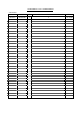
RECORDS OF REVISION LQ038Q5DR01 SPEC No. DATE PAGE SUMMARY NOTE LD-22113 Feb.3.
LD-22113-1 NOTICE This publication is the proprietary of SHARP and is copyrighted, with all rights reserved. Under the copyright laws, no part of this publication may be reproduced or transmitted in any form or by any means, electronic or mechanical for any purpose, in whole or in part, without the express written permission of SHARP. Express written permission is also required before any use of this publication may be made by a third party.
LD-22113-2 (1) Application This specification literature applies to color TFT-LCD module ,LQ038Q5DR01. (2) Summary And Features This module is a color active matrix LCD module incorporating amorphous silicon TFT (Thin Film Transistor). It is composed of a color TFT-LCD panel, driver ICs, control-PWB, FPC, frame, front shielding case, back-light unit. Graphics and texts can be displayed on a 320×3×240 dots panel with 262,144 colors by supplying. DC/AC inverter isn’t composed. The 3.
LD-22113-3 (4) Input Terminal 4-1) TFT-LCD Panel Driving Part Used connector: KX14-40K5D-VIE (JAE Co. , Ltd) Fit connector Pin No. 1 2 3 4 5 6 7 8 9 10 11 12 13 14 15 16 17 18 19 20 21 22 23 24 25 26 27 28 29 30 31 32 33 34 35 36 37 38 39 40 Symbol GND VCC Hsync G3 T0 G4 T1 G5 HVR GND GND B0 CLK B1 GND B2 R0 GND R1 B3 R2 B4 GND B5 R3 GND R4 Vsync R5 TEST GND TEST G0 TEST G1 TEST G2 ENAB VCC GND : KX15-40KLDLE(JAE Co.
LD-22113-4 【Note 4-1】 Hsync positive Vsync positive 【Note 4-2】 The horizontal display start timing is settled in accordance with a rising timing of ENAB signal. In case ENAB is fixed “Low”, the horizontal start timing is determined as described in Fig3-A. (Don’t keep ENAB “High” during operation.(Fig3-B).
LD-22113-5 (6)Electrical characteristics 6-1)TFT-LCD panel driving section Parameter Supply voltage +3.3V Current dissipation Permissive input ripple Input Low voltage Input High voltage Table 6-1 Symbol Min. Vcc +2.9 − I cc − VRF − VIL VIH 0.7VCC GND=0V,Ta=25℃ Max. Unit Remarks +3.7 V 【Note 6-1】 180 mA 【Note 6-2,3】 100 mVpp 0.3VCC V 【Note 6-4】 − V VI=0V 1.0 µA 【Note 6-5】 VI=VCC 75 µA 【Note 6-5】 VI=0V 75 µA 【Note 6-6】 VI=VCC 1.0 µA 【Note 6-6】 VI=0V 150 µA 【Note 6-7】 VI=VCC 2.0 µA 【Note 6-7】 Typ. +3.
LD-22113-6 【Note 6-4】CK,R0∼R5,G0∼G5,B0∼B5,Hsync,Vsync,ENAB,HVR 【Note 6-5】CK,R0∼R5,G0∼G5,B0∼B5,Hsync,Vsync 【Note 6-6】ENAB 【Note 6-7】HVR 6-2)Backlight driving section The backlight system is an edge-lighting type with single CCFT (Cold Cathode Fluorescent Tube). The characteristics of Lamp are shown in the following table. Table 6-2 Parameter Symbol Min. Typ. Max. Unit Remarks IL=5.5mArms lamp voltage VL7 470 530 590 Vrms lamp current IL 5.0 5.5 6.0 mArms ordinary state PWM dimming state − − ILB 9.
LD-22113-7 7) Timing Characteristics of input signals Timing diagrams of input signal are shown in Fig.3-A, Fig.3-B. 7-1) Timing characteristics Table 7-1 Parameter Symbol MIN TYP MAX Unit Remarks Clock frequency 1/Tc 4.5 6.3 6.8 MHz High time Tch 50 ns − − Low time Tcl 50 ns − − Data Setup time Tds 50 ns − − Hold time Tdh 50 ns − − Hsync-Clock phase difference THc 50 120 ns − Hsync-Vsync phase difference TVh 0 TH-10 µs − Note) In case of lower frequency, the deterioration of display quality, flicker etc.
LD-22113-8 7-4) Input Data Signals And Display Position on The Screen UP D1,DH1 D2,DH1 D1,DH2 D2,DH2 D3,DH1 D320,DH1 D1,DH3 R G B D1,DH240 D320,DH240 Display position of input data (H,V)
LD-22113-9 (8) Input Signals, Basic Display Color And Gray Scale of Each Color Data signal Colors & Gray scale Gray Scale R0 R1 R2 R3 R4 R5 G0 G1 G2 G3 G4 G5 B0 B1 B2 B3 B4 B5 Basic color Gray Scale of red Gray Scale of green Gray Scale of blue Black − 0 0 0 0 0 0 0 0 0 0 0 0 0 0 0 0 0 0 Blue − 0 0 0 0 0 0 0 0 0 0 0 0 1 1 1 1 1 1 Green − 0 0 0 0 0 0 1 1 1 1 1 1 0 0 0 0 0 0 Cyan − 0 0 0 0 0 0 1 1 1 1 1 1 1 1 1 1
LD-22113-10 (9)Optical Characteristics Table 9-1 Ta=+25℃, VCC=+3.3V Symbol Condition Min. Typ. Max. Unit Remarks θ6 − 60 65 degree 【Note 9-1,4】 θ12 − 35 40 degree CR≧5 θ3 − 60 65 degree θ9 − − 【Note 9-2,4】 Contrast ratio CRmax Optimum 100 τr θ=0° − 【Note 9-3,4】 Response Rise 30 60 ms τd − time Fall 50 100 ms − 【Note 9-5】 Luminance Y IL=5.5mArms 350 450 cd/m2 【Note 9-5】 White chromaticity x 0.263 0.313 0.363 IL=5.5mArms y 0.279 0.329 0.
LD-22113-11 【Note 9-1】 Viewing angle range is defined as follows. Normal line θ92 θ θθ6 11 θ 12 θθ3 2 6 o’clock direction Definition for Viewing Angle 【Note 9-2】Contrast ratio is defined as follows: Photo detector output with LCD being "white" Contrast ratio(CR)= Photo detector output with LCD being "black" 【Note 9-3】Response time is obtained by measuring the transition time of photo detector output, when input signals are applied so as to make the area "black" to and from "white".
LD-22113-12 【Note 9-6】Lamp is consumables. In the following condition, the lamp life time is 20,000 hours as the reference value and it is not guaranteed in this specification sheet by SHARP. Lamp life time is defined that it applied either ① or ② under this condition. ※Continuous turning on at Ta = 25 oC, IL = 5.5mA rms and PWM dimming 80%~5% (IL= 9.0mArms Ta= 25℃). ①Brightness becomes 50% of the original value under standard condition. ②Kick-off voltage at Ta = −30 oC exceeds maximum value (1700Vrms).
LD-22113-13 (10) Mechanical Characteristics 10-1) External Appearance Do not exist extreme defects. (See Fig. 1) 10-2) Panel Toughness The panel shall not be broken ,when 19N is pressed on the center of the panel by a smooth sphere having 15 mm diameter. Caution:In spite of very soft toughness, if, in the long-term, add pressure on the active area, it is possible to occur the functional damage.
LD-22113-14 12-2) Precautions in Mounting Polarizer which is made of soft material and susceptible to flaw must be handled carefully. Protective film (Laminator) is applied on the surface to protect it against scratches and dirties. It is recommended to peel off the laminator immediately before the use, taking care of static electricity. Precautions in peeling off the laminator A) Working Environment When the laminator is peeled off, static electricity may cause dust to stick to the polarizer surface.
LD-22113-15 E) If water dropped, etc. remains stuck on the polarizer for a long time, it is apt to get discolored or cause stains. Wipe it immediately. F) As a glass substrate is used for the TFT-LCD panel, if it is dropped on the floor or hit by something hard, it may be broken or chipped off. G) Since CMOS LSI is used in this module, take care of static electricity and take the human earth into consideration when handling.
LD-22113-16 solvent, adhesive, resin, etc. which generate these gasses, causes corrosion and discoloration of the modules. Therefore, please avoid these use. Epoxy resin (amino series curing agent), silicone adhesive material (dealcoholization series and oxime series), Tray forming agent (azo compound) etc, in the cabinet or the packing materials may induce abnormal display with polarizer film deterioration. Be sure to confirm the component of them.
LD-22113-17 ・Please note that ventilation is improved and consider the installation such as ventilators in the warehouse. ・ Please manage so that there is no rapid temperature change more than natural environment. ⑥Period :about 3 months ⑦Opening of the package:In order to prevent the LCD module from breakdown electrostatic charges, please control the room humidity over 50%RH and open the package taking sufficient countermeasures against electrostatic charges, such as earth, etc.
LD-22113-18 Reliability Test Conditions for TFT-LCD Module Table 14 Remark) Temperature condition is based on operating temperature conditions on (5)-Table 5-1. No.
LCY00044−17 LD-22113-19
LCY00044−18 LD-22113-20 Fig.2.
TH:(THe+308)CK∼440CK C C V 7 . 0 C C V 7 . 0 C C V 3 . 0 C C V 3 . 0 Horizontal sync. signal THp (Hsync) TH T 0.5VCC Number of clock Data signal (R0∼R5,G0∼G5, B0∼B5) 0.5VCC C C V 3 . 0 C C V 3 . 0 C C V 3 . 0 Clock signal (CK) Tc Tch Tcl THc Horizontal invalid data period D1 D2 THe Tds Tdh D3 Number of H-data D319 D320 Horizontal invalid data period THd C C V 7 . 0 C C V 3 . 0 Tes Data enable signal (ENAB) Tep TV C C V 7 . 0 TVp C C V 7 . 0 Horizontal sync.
TH:380CK∼440CK C C V 7 . 0 C C V 7 . 0 C C V 3 . 0 C C V 3 . 0 Horizontal sync. signal THp (Hsync) TH T 0.5VCC Tds Tdh Data signal (R0∼R5,G0∼G5, B0∼B5) 0.5VCC C C V 3 . 0 K C 2 7 C C V 3 . 0 C C V 3 . 0 Clock signal (CK) Tc Tch Tcl THc Horizontal invalid data period D1 D2 Number of H-data Number of clock D3 D319 D320 Horizontal invalid data period THd Data enable signal (ENAB) TV C C V 7 . 0 TVp C C V 7 . 0 Horizontal sync. signal (Hsync) C C V 3 . 0 (Vsync) C C V 7 .
LD-22113-23 LCY00044-21 Fig.4.
Technical Document LCD Specification LCD Group NORTH AMERICA Sharp Microelectronics of the Americas 5700 NW Pacific Rim Blvd. Camas, WA 98607, U.S.A. Phone: (1) 360-834-2500 Fax: (1) 360-834-8903 www.sharpsma.com TAIWAN Sharp Electronic Components (Taiwan) Corporation 8F-A, No. 16, Sec. 4, Nanking E. Rd. Taipei, Taiwan, Republic of China Phone: (886) 2-2577-7341 Fax: (886) 2-2577-7326/2-2577-7328 CHINA Sharp Microelectronics of China (Shanghai) Co., Ltd.