STULZ the natural choice Instructions CyberAir 3 CW Precision Air Conditioning Units 380-415/3/50 Original instructions Index 18 Issue 8.
Contents 1. Safety ...........................................................................................................................3 1.1 Marking..............................................................................................................................................3 1.2 Safety instructions .............................................................................................................................3 1.3 Safety and environmental requirements ....................
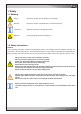
1. Safety 1.1 Marking Danger - threatening danger, grievous bodily harm and death Attention - dangerous situation, light bodily injury and material damage Information - important information and application notice ESD note - risk of damaging electronical components 1.2 Safety instructions General These operating instructions contain basic information which is to be complied with for installation, operation and maintenance.
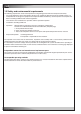
1.3 Safety and environmental requirements The following requirements relate to the operation of refrigerating plants within the European Community. - The used components must correspond to the pressure equipment guide-line EC/97/23 and EN 378 part 1-4. - Independent of the design, the equipment and inspection before the delivery, also the operator of such plants has duties according to EN 378 and national regulations.
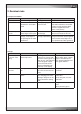
2. Residual risks Transport, Installation Area Cause Danger Safety note Under the unit Defective lifting device Bruising Keep away from under the unit Beside the unit Uneven or insufficient foundation or raised floor stand Bruising by tipping over of the unit Make sure, the foundation is even and stable and that the raised floor stand is correctly mounted. Wear protective equipment (helmet, gloves, safety shoes).
Operation Area Cause Danger Safety note Unit bottom, eventually raised floor Accumulation of condensate and water discharge by too small or clogged drain pipe Corrosion and development of mould by moistness. Humidity in combination with electric connections. De-energize water discharge area. Electrical alimentation Falsely dimensioned cables or protection devices Short-circuit, fire, acid vapours Correctly design alimentation cables and protection elements. Wear protective mask.
3. Transport / Storage 3.1 Delivery of units Stulz A/C units are mounted on pallets and packed several times in plastic film. They must always be transported upright on the pallets. Construction of protective covering (from inside to outside) 1. 2. 3. Neopolene cushioning Shrink film Additional board in container shipments The following information can be found on the packing.
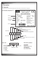
4. Description 4.1 Type code The type code represents the unit variant of your A/C unit and can be found on the rating plate. The rating plate is located in the door in front of the electrical compartment. ASD 800 CW Unit type internal part no. A99648 Water/Glycol Order number + alternative 16 --Serial no.
4.2 Intended use This A/C unit is used to control room temperature and air humidity. The A/C unit is designed for indoor installation. Any use beyond this is not deemed to be use as intended. STULZ is not liable for any damage resulting from such misuse. The operator alone bears the risk. 4.3 Function of the A/C unit The A/C unit is exclusively operated by the controller in the front panel and the main switch in the electric box.
5. Technical data 5.1 Application limits The STULZ CyberAir 3 CW units are provided for operation within the following ranges: - Admissible return air conditions: Temperature: Lower limit: 18°C Upper limit: 35°C Humidity: Lower limit: Upper limit: 5,5°C dew point 60% r.h. and 15°C dew point - Chilled water conditions: min. temperature at the unit inlet: 5°C min temp. difference with 5°C EWT: 5 K max. head pressure: 16 bar - Storage conditions: Temperature [°C]: -20 - +42 Humidity [% rel. h.
5.2 Technical Data - ASD ...
5.4 Technical Data - ASD ... CW2 Modell Type CW-Kälteleistung CW-cooling capacity 24°C/50% r.F. r.H.
5.6 Dimensional drawings 35 Cabinet size 2 Side view (for all sizes) 1980 10 Cabinet size 1 950 890/980* 1400 * for cabinet size 7 Cabinet size 3 Cabinet size 4 1750 2200 EN /08.
Cabinet size 5 2550 Cabinet size 7 3110 EN /08.
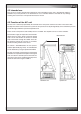
6. Installation 6.1 Positioning Check that the installation site is appropriated for the unit weight, which you can read in the technical data. The A/C unit is designed for the inside installation on a level base. The solid base frame contributes significantly to an even weight distribution. When selecting the installation site take into account the necessary clearances for the maintenance and the air flow.
6.2 Water piping connection External water circuit To seal the water circuit you must connect the unit to a chilled water ring mains, which contains for the generation of cold water either a chiller or a dry cooler or cooling tower. If the water quality is insufficient, we recommend the additional installation of a fine mesh strainer.
6.2.
D 6.2.2 Pipe entrance area - Downflow version, single circuit At Downflow units the supply pipes and cables are introduced from the bottom through openings in the base plate. The unit bottom views are displayed following.
D Bottom view ASD 800/950 CW Water inlet Power supply Water outlet Control lines HWR inlet Humidifier inlet/ outlet HWR outlet Condensate drain Unit rear side ASD 1000/1180 CW Water inlet Power supply Water outlet Control lines HWR inlet Humidifier inlet/ outlet HWR outlet Condensate drain Unit rear side HWR: Hot water reheat Diameter of the chilled water lines ASD...CW 800 950 1000 1180 bauseits Ø by client mm 54 64 external Außengewinde thread inch Zoll R2 R2 EN /08.
ASD 1250/1550 CW Water inlet Diameter of the chilled water lines mm R2 64 1250 1550 bauseits Ø by client inch Zoll ASD...CW external Außengewinde thread Water outlet Bottom view Unit rear side Power supply Control lines HWR inlet Humidifier inlet/ outlet HWR outlet Condensate drain EN /08.
Water inlet Water outlet bauseits Ø by client inch Zoll mm R 2 1/2 64 1800 2100 external Außengewinde thread ASD...CW Diameter of the chilled water lines ASD 1800/2100 CW D Bottom view Unit rear side Power supply Control lines HWR inlet HWR outlet Humidifier inlet/ outlet Condensate drain EN /08.
U 6.2.3 Pipe entrance area - Upflow units, single circuit At Upflow units the supply pipes and cables are introduced from the left or right side through openings in the side wall. Connection from the left Connection from the right ASU ...
6.2.4 Pipe entrance area - Downflow version, dual circuit At Downflow units the supply pipes and cables are introduced from the bottom through openings in the base plate. The unit bottom views are displayed following.
ASD 670 CW2 Bottom view CW outlet 2 Power supply Control lines HWR inlet Humidifier inlet/ outlet CW inlet 1 CW outlet 1 HWR outlet CW inlet 2 Condensate drain unit rear side ASD 810 CW2 CW inlet 2 CW outlet 2 Power supply Humidifier inlet/ outlet Control lines CW inlet 1 CW outlet 1 unit rear side HWR inlet HWR outlet Condensate drain Diameter of the chilled water lines ASD...CW2 670 810 bauseits Ø by client mm 42 54 Außengewinde external thread Zoll inch R 1 1/2 R2 EN /08.
ASD 1070 CW2 Humidifier inlet/ outlet CW inlet 1 CW outlet 1 Diameter of the chilled water lines mm R2 64 1070 Ø by client bauseits inch Zoll ASD...CW2 external thread Außengewinde CW inlet 2 Bottom view CW outlet 2 unit rear side Power supply Control lines HWR outlet HWR inlet Condensate drain CW: chilled water HWR: hot water reheat 1: circuit 1 2: circuit 2 EN /08.
ASD 1170 CW2 Humidifier inlet/ outlet CW outlet 1 CW inlet 1 Diameter of the chilled water lines mm R2 64 1170 bauseits Ø by client Zoll inch ASD...CW2 Außengewinde external thread CW inlet 2 Bottom view CW outlet 2 unit rear side Power supply Control lines HWR inlet HWR outlet Condensate drain CW: chilled water HWR: hot water reheat 1: circuit 1 2: circuit 2 EN /08.
U 6.2.5 Pipe entrance area - Upflow units, dual circuit At Upflow units the supply pipes and cables are introduced from the left or right side through openings in the side wall. In units of version CW2 there are 4 water connections in total (2x water inlet, 2x water outlet). Connection from the left Connection from the right The openings R1 and R5 can not be used.
6.3 Electrical connection Ensure that the electric cables are de-energized. The electric cables are only to be connected by an authorised specialist. The unit must dipose of an effective earthing. Do not touch electronical components, without taking care of protective ESD measures. The power supply system on site and the pre-fuses must be designed for the total current of the unit (see technical data).
Insertion of the power supply cable 1. cabinet size 1 - Downflow 2. cabinet size 1 - Upflow 3. cabinet size 2-7 - Downflow 4. cabinet size 2-5 - Upflow 3. 1. 2. 4. System with external pump Choose a power switch and a contactor in respect of the pump capacity. A power switch and a contactor can be located in the electric box. Caution! The power supply of the pump can not be obtained via the master switch as the master switch is designed according to the current consumption of the standard unit.
7. Commissioning The unit must be installed and connected in accordance with the chapter on "installation" before initial commissioning. • • • • • Make sure that the master switch is off and the unit is de-energized. Open the electrical compartment door of the unit using the key provided. Check whether all power switches and control-circuit fuses in the electrical section of the unit are switched off. Retighten all screw connections in the electric cabinet. Verify the smooth function of the contactors.
8. Maintenance 8.1 Safety instructions All maintenance work is to be carried out under strict compliance with the country-specific accident prevention regulations. In particular we refer to the accident prevention regulations for electrical installations, refrigerating machines and equipment. Non-compliance with the safety instructions can endanger people and the environment. Maintenance work is only to be carried out on the units by authorized and qualified specialist staff.
8.3 Air circuit Heat exchanger (CW-coil) The heat exchanger consists of copper tubes with aluminium fins. If refrigerant leaks occur, they should be searched for at the heat exchanger. Beyond that, the heat exchanger is exposed to the air pollution, the particles of which settle at the fins and reduce the heat transmission the same as raise the air resistance. The latter shows when the fan current increases.
9. Malfunction Alarm message Cause for alarm Cause Elimination 1. Fan motor defective. Fan speed too low. Check fan motor on voltage continuity and current consumption. Fan mechanically blocked? Check air filter. Exchange V-belt. Clean hoses and check whether they are kinked . C7000: Airflow failure C1002: FLO# Differential pressure for airflow switch has triggered. C7000: Sensor # error C1002: not existant The tolerance to the average 1.
10. Dismantling and disposal The A/C unit can only be dismantled by qualified specialists. Switch off the A/C unit at the controller and at the master switch. Switch off power conducting cables to the unit and secure them against being switched on again. Disconnect the A/C unit from the de-energized network. If glycol or similar additives had been used, this liquid has to be collected and disposed in an appropriate manner and may under no circumstances be introduced in the local waste water system.
11. Contents of the CE Declaration of Conformity The undersigned STULZ GmbH Klimatechnik Holsteiner Chaussee 283 22457 Hamburg hereby confirms that the units listed below, in the version marketed by us, fulfil the requirements of the harmonised EC directives and EC safety standards listed below. In the case of a modification of the equipment not co-ordinated with us this declaration loses its validity. Air conditioning unit Cyber Air 3 ... CW ASD 320 ... ASD 420 ... ASD 550 ... ASD 650 ... ASD 800 ...
12.1 Steam humidifier The steam humidifier is an optional extra for your A/C unit. It is installed complete and integrated within the function and method of operation of the A/C unit. Details concerning the connection assignment for the power supply can be found in the electrical diagrams in the appendix. 12.1.
Danger that may arise from the unit DANGER! Danger of electric hazard! The steam humidifier OEM2 is operated with mains voltage. One may get in touch with live parts when the unit is open. Touching live parts may cause severe injury or danger to life. Prevention: Before carrying out any work set the steam humidifier OEM2 out of operation as described in chapter 12.1.3.5 (switch off the unit, disconnect it from the mains and stop the water supply) and secure the unit against inadvertent power-up.
12.1.1.
12.1.1.3 Configuration of the control unit ECCM/S Setting the capacity limitation “Sx%” Use the potentiometer “Sx%” to set the capacity limitation in % of the maximum capacity (setting range: 25...100%, factory setting: 100%). Setting the control signal With the jumpers on jumper block “JP1” you can set the control signal. The control signal is adjusted on 0-10V, none of the jumpers "mA", "SP", "2P" on jumper block "JP1" may be set for this.
12.1.2 Supply connections The steam humidifier is installed and electrically connected in the A/C unit. The local regulations of the water supply company are to be complied with when making the hydraulic connection. We recommend the installation of an Aqua-stop valve in the water supply of the humidifier. In addition to this, the room, in which the A/C unit with the humidifier is installed, should be equipped with a water detection system. Legend: 1 Level sensor 2 Steam outlet connector ø22.
12.1.3 Operation 12.1.3.1 Function of the display and operating elements on the control unit ECCM/S 1 Drain/Info key – press key shortly: opens and closes the drain valve (manual draining). Note: the drain valve is automatically closed after 10 minutes. – press key for a extended period of time: activating the info mode 2 Error indication (red LED) – in normal operating mode The LED lights in case of a malfunction of the unit. Further operation is no longer possible, the heating voltage is interrupted.
12.1.3.2 Commissioning Proceed as follows when putting the unit into operation: 1. 2. 3. 4. Examine the steam humidifier and installation for possible damage. Open the shut-off valve (if existant) in the water supply line. Switch on control fuse and humidifier power switch in electric box. Switch on main switch. Adjust the humidity set value at the C7000 controller.
12.1.4 Fault elimination Important! Most operational malfunctions are not caused by faulty equipment but rather by improper installation or disregarding of planning guidelines. Therefore, a complete fault diagnosis always involves a thorough examination of the entire system. Often, the steam hose connection has not been properly executed, or the fault lies with the humidity control system. 12.1.4.
12.1.4.3 Malfunction lists “Warning” yellow LED blinks “Error” red LED blinks 1x Control board defective --- 2x Max. filling level of steam cylinder reached 3x Permissible filling time exceeded for more than 20 minutes (first automatic cleaning cycle) --- Cause Remedy Control board defective Please contact your unit supplier. Water conductivity too low (after initial operation). Water conductivity too low for type of steam cylinder. Phase failure heating voltage. Wait.
12.1.4.4 Replacement of fine-wire fuse on the control unit ECCM/S If the fine-wire fuse on the control unit ECCM/S blows this is usually due to a faulty coil of the inlet or drain valve or the main contactor. Therefore you should test these components before replacing the fuse. To replace the fine-wire fuse proceed as follows: 1. Set the steam humidifier OEM2 out of operation as described in chapter 12.1.3.5, separate the unit from the mains and secure it against unintentional switching on.
12.2 Reheat The reheat is an optional extra for your A/C unit. It is installed complete and integrated in the function and method of operation of the A/C unit. It is used to heat up the air. The following versions of the heater are available: - Electrical reheat - Hot water reheat (HW) - Hotgas reheat (HG) Description Electrical reheat HW reheat HG reheat The HW reheat is to be connected to an external hot water circuit. The water supply is controlled via an electrically actuated HW valve.
Installation The reheats are installed and connected in the A/C unit. The HW reheat is to be connected on site to the external hot water circuit. The pipelines are to be routed out of the A/C unit. The thread sizes for the connection piping of the HW reheat are listed in the following table.
12.3 Air side connection 12.3.1 Unit base L3 E 450 The unit base is available in the versions: open, with damper, with flexible connection or with supply grilles. The unit base can be installed in two ways, with the opening to the front or with the opening to the rear.
Unit base with grilles / L5 The standard grilles are equipped with horizontal fins which can be adjusted to conduct the air which is blown out. L5: middle position for size 5 and 7 Unit base with flexible connection L2 300 150 Unit base with damper L2 38 300 120 175 L2 345 Cabinet size 7: Caution! Each of the unit base versions must be screwed to the unit by 4x M10 screws! EN /08.
12.3.2 Filter base The filter base is designed for the option "suction from bottom". With this option for upflow units the front panels are not provided with an air inlet perforation as otherwise usual. The air is drawn in from the bottom, in consequence there is no unit bottom plate, but supporting bars instead, on which compressors and other components are mounted.
For the air side connection on top of the unit exist different options, which are delivered in a completely assembled condition. On the installation site these set-ups must be set upon the unit and must be connected to it. 12.3.3 Duct 500 / 800 The duct will be set on top of the unit and be screwed with the unit. The duct is available with two different heights (500 or 800 mm) for all units.
12.3.4 Discharge plenum The discharge plenum is availale in two different versions for all units. The discharge plenum will be set on top of the unit and be screwed with the unit. 500 400 Discharge plenum with front grilles L1 L1 D B C T 400 500 400 Discharge plenum with front and side grilles L1 D B L1 T1 C T Only one front grille for size 1, 2. Three front grilles for size 7.
12.3.5 Bag filter top 500 The bag filter is available for all downflow units. The bag filter serves for the pre- filtration of the air which is sucked in and can be obtained in the qualities F6, F7 and F9 (according to EN779). The bag filter top will be set on top of the unit and be screwed with the unit. B 884 12.3.6 Sound insulation plenum 500/800 The sound insulation plenum is available for all units. The plenum will be set on top of the unit and be screwed with the unit. B = unit width EN /08.
12.3.7 Adapter plate with damper or flexible connection - Connection on the unit The adapter plate serves to attach a damper or a flexible connection on top of the unit or a duct. First install the actuator onto the louver shaft on the right side looking at the unit front. Then fix the louver with the actuator on the adapter plate. Now mount the adapter plate with pre-mounted louver on the unit top by means of a screw connection.
Adapter plate with damper or flexible connection - Connection under the unit The adapter plate serves to attach a damper or a flexible connection under the unit. First install the actuator onto the louver shaft on the right side (at the front for Cyberir 3 CW, construction size 1 and 2) looking at the unit front. Then fix the louver with the actuator under the adapter plate. Now mount the adapter plate with pre-mounted louver on the floor stand frame by means of bolts.
ASD...CW Cabinet Baugröße size 1 2 3 4 5 7 A mm 950 1400 1750 2200 2550 3110 B mm 92 145 247 282 257 237 C mm 675 1005 1400 750 950 1200 D mm 210 260 258 210 195 185 E mm 600 550 550 600 600 675 F mm - - - 1342 1492 1805 G mm - - - 750 950 1200 H mm 175 175 175 120 120 120 J mm - - - 260 245 350 550 550 510 K mm Flexible connection height for all units: 150 mm ASD...
Airflow straightener (for Downflow units only) With the application of an airflow straightener grid, which is mounted onto the fan injection nozzle, the sound emission is reduced. The electrical fan power consumption is increased. In the diagrams below the absolute power increase and the sound reduction is displayed in dependance of the air volume flow for the construction sizes 1-7.
12.4 Raised floor stand The floor stand is used to adjust the height of the A/C unit to the existing raised floor and consists of an encircling rectangular profile of galvanized steel with adjustable screw sockets. Anti vibration compound is recommended between concrete floor and base plate.
Connecting the bars Angle Connection (View from below) Butt Joint Cross Connection Minimum distances and mounting instructions - - - Please observe that the floor stand must be decoupled from the surrounding floor plates by damping insertions and that mafund plates are laid under the floor supports. Raised floor stand Y The raised floor cutting (notch) should at least be 15° and must not have any contact to the raised floor stand, which could result in bone-conduction. Z (min.
Detail of raised floor connection 1 2 3 4 5 6 7 8 9 10 11 12 13 Raised floor stand Adjustable support plate Adjusting nut Support pipe Support base Mafund strips Raised floor cut out angle Continuous seal profile Before unit installation Raised floor plate Angled bracket Permanently elastic seal Fixing Sealing detail when distance Z < 100 mm Sealing detail when distance Z > 100 mm Other mounting options (e.g.