
Specifications

SPEC No.
LC99213A
MODEL No.
LM10V332
PAGE
22
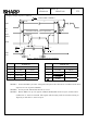
10. Cautions
1)
Industrial(Mechanical) design of the product in which this LCD module will be incorporated must
be made so that the viewing angle characteristics of the LCD may be optimized.
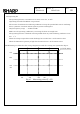
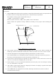
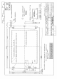
This module’s viewing angle is illustrated in Fig.12.
θy MIN. < viewing angle <θy MAX.
(For the specific values ofθy MIN., andθy MAX., refer to the table8)
Please consider the optimum viewing conditions according to the purpose when installing the
module.
Fig.12 Definition of viewing angle
2)
This module should be installed using mounting holes of metal bezel. When installing the
module,pay attention and handle carefully not to allow any undue stress such as twist or bend.
3) Since the front polarizer is easily damaged. Please pay attention not to scratch on its face.
It is recommended to use a transparent acrylic resin board or other type of protective panel on
the surface of the LCD module to protect the polarizer, LCD panel, etc..
4)
If the surface of the LCD panel is required to be cleaned, wipe it swiftly with cotton or other soft
cloth. If it
is not still clear completely, blow on and wipe it.
5)
Water droplets, etc. must be wiped off immediately since they may cause color changes, staining,
etc., if it remained for a long time.
6)
Since LCD is made of glass substrate, dropping the module or banging it against hard objects
may cause cracking or fragmentation.
7) Since CMOS LSIs are equipped in this module, following countermeasures must be taken to
avoid electrostatics charge.
Panel surface
Viewing direction +θy
θ
y=0
°
(Normal line)
-θy