
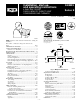
Operating instructions

NOTE: Read the entire instruction manual before starting the
installation.
This symbol → indicates a change since the last issue.
Index Page
DIMENSIONAL DRAWING........................................................2
SAFETY CONSIDERATIONS.....................................................3
Clearances to Combustibles......................................................3
ELECTROSTATIC DISCHARGE (ESD) PRECAUTIONS ....3-4
INTRODUCTION..........................................................................4
APPLICATIONS ......................................................................4-11
General ......................................................................................4
Upflow Applications..............................................................4-7
Downflow Applications.........................................................7-8
Horizontal Left (Supply-Air Discharge) Applications .........8-9
Horizontal Right (Supply-Air Discharge) Applications...10-11
LOCATION ............................................................................11-13
General...............................................................................11-12
Furnace Location Relative to Cooling Equipment ................12
Hazardous Locations...............................................................13
INSTALLATION....................................................................13-17
Leveling Legs (If Desired).....................................................13
Installation In Upflow or Downflow Applications................13
Installation In Horizontal Applications..................................13
Air Ducts............................................................................13-16
Filter Arrangement..................................................................16
Bottom Closure Panel........................................................16-17
Gas Piping...............................................................................17
ELECTRICAL CONNECTIONS...........................................17-19
115-v Wiring......................................................................18-19
24-v Wiring.............................................................................19
Accessories..............................................................................19
Wiring Diagram ......................................................................20
DIRECT VENTING ...............................................................19-30
Removal of Existing Furnaces from
Common Vent Systems.....................................................19
Combustion-Air and Vent Piping .....................................19-27
Concentric Vent and Combustion-Air Termination
Kit Installation..............................................................27-30
Multiventing and Vent Termination.......................................30
CONDENSATE DRAIN ........................................................30-32
General ....................................................................................30
Application..............................................................................30
Condensate Drain Protection..................................................30
SEQUENCE OF OPERATION..............................................30-33
Heating Mode ....................................................................30-32
Cooling Mode .........................................................................32
Continuous Blower Mode.......................................................32
Heat Pump Mode...............................................................32-33
Component Test......................................................................33
START-UP PROCEDURES ..................................................33-42
General ....................................................................................33
Prime Condensate Trap With Water.................................33-34
Purge Gas Lines......................................................................34
Adjustments .......................................................................34-42
Set Gas Input Rate ............................................................34-41
Set Temperature Rise ........................................................41-42
Blower Off Delay (Heat Mode).............................................42
Set Thermostat Heat Anticipator............................................42
CHECK SAFETY CONTROLS..................................................42
Check Primary Limit Control.................................................42
Check Pressure Switch ...........................................................42
CHECKLIST...........................................................................42-43
A93040
®
ama
CANADIAN GAS ASSOCIATION
APPROVED
R
As an ENERGY STAR®
Partner, Bryant Heating &
Cooling Systems Com-
pany has determined that
this product meets the EN-
ERGY STAR® guidelines
for energy efficiency.
REGISTERED QUALITY SYSTEM
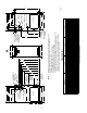
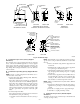
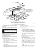
Fig. 1—Multipoise Orientations
A93041
UPFLOW
DOWNFLOW
HORIZONTAL
LEFT
AIRFLOW
AIRFLOW
AIRFLOW
AIRFLOW
HORIZONTAL
RIGHT
installation, start-up,
and operating instructions
4-WAY MULTIPOISE
FIXED-CAPACITY DIRECT-VENT
CONDENSING GAS FURNACE
Cancels: II 340M-40-5 II 340M-40-6
4-99
340MAV
Series E
—1—