
Service manual


21
R-820BK
R-820BW
TEST PROCEDURES
PROCEDURE
LETTER
COMPONENT TEST
If the control unit responds by clearing with a beep the key unit is faulty and must be replaced. If the
control unit does not respond, it is faulty and must be replaced. If a specific pad does not respond,
the above method may be used (after clearing the control unit) to determine if the control unit or key
pad is at fault.
5. Reconnect all leads removed from components during testing.
6. Re-install the outer case (cabinet).
7. Reconnect the power supply cord after the outer case is installed.
8. Run the oven and check all functions.
N RELAY TEST
5
4
3
21
09876
G 8 G 7 G 6 G 5 G 4 G 3 G 2 G 1
G12 G11 G10 G 9
POWER
LEVEL
MINUTE
PLUS
BAKE
CUSTOM
HELP
CLOCK
GRILL
ROAST
REHEAT CONVEC
STOP
CLEAR
START
TOUCH ON
PIZZA
GRILL
ROAST
DEFROST
KITCHEN
TIMER
POPCORN
COOK
1. Disconnect the power supply cord, and then remove outer case.
2. Open the door and block it open.
3. Discharge high voltage capacitor.
4. Disconnect the leads to the primary of the power transformer.
5. Ensure that these leads remain isolated from other components and oven chassis by using insulation
tape.
6. After that procedure, re-connect the power supply cord.
7. Remove the outer case and check voltage between Pin No. 1 of the 3 pin connector (A) and the
common terminal of the relay RY6 on the control unit with an A.C. voltmeter.
The meter should indicate 120 volts, if not check oven circuit.
Shut off, Cook and Heater Relay Test
These relays are operated by D.C. voltage
Check voltage at the relay coil with a D.C. voltmeter during the microwave cooking operation, grill
cooking operation, or convection cooking operation.
DC. voltage indicated ............. Defective relay.
DC. voltage not indicated ........ Check diode which is connected to the relay coil. If diode is good, control
unit is defective.
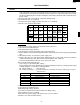
RELAY SYMBOL OPERATIONAL VOLTAGE CONNECTED COMPONENTS
RY1 Approx. 24.0V D.C. Convection motor
RY2 Approx. 24.0V D.C. Power transformer
RY3 Approx. 24.0V D.C. Grill heaters (Top)
RY4 Approx. 24.0V D.C. Bottom heater
RY5 Approx. 24.0V D.C. Fan motor
RY6 Approx. 24.0V D.C. Oven lamp / Turntable motor
8. Disconnect the power supply cord, and then remove outer case.
9. Open the door and block it open.
10.Discharge high voltage capacitor.
11.Reconnect all leads removed from components during testing.
12.Re-install the outer case (cabinet).
13.Reconnect the power supply cord after the outer case is installed.
14.Run the oven and check all functions.